Kio3 interface – Elecraft K3 Assembly Manual User Manual
Page 28
27
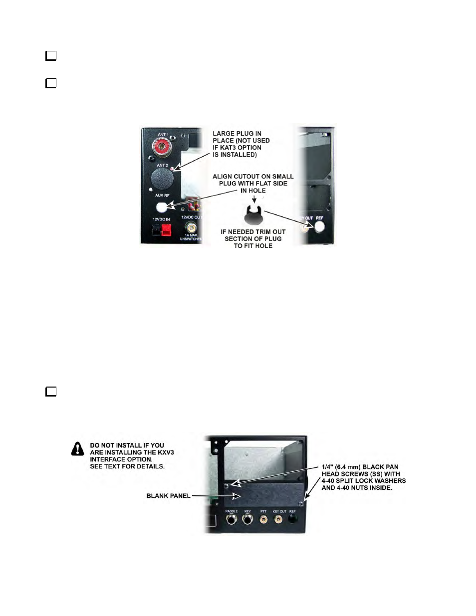
If you installed the KANT3 board, the hole for the ANT2 jack is not used. Insert the larger of the hole plugs
in the opening until it clicks in place (see Figure 30).
If you do not have the K3EXREF option, insert one of the smaller hole plugs in the REF connector at the
bottom right. Align the open side of the plug with the flat side of the hole as shown in Figure 30. If the plug does
not have a cutout, use your diagonal cutters to clip out a section of the plug so it will fit into the hole. Similarly,
install the other small plug in the AUX RF opening if the subreceiver connector was not installed.
Figure 30. Installing Rear Panel Hole Plugs.
KIO3 Interface
KIO3 Description
All rear-panel audio and digital/computer I/O is routed through the KIO3. The KIO3 is made up of three PC
boards: Main, Audio I/O and Digital I/O. The Main KIO3 board plugs directly into the RF board, while the
Audio and Digital I/O modules plug into the KIO3 main board. All three boards can be upgraded to meet future
requirements. See Theory of Operation, KIO3, in the K3 Owner’s Manual for more information.
KIO3 Interface Installation Procedure
If you have purchased the KXV3 option with your kit, go to the Installation Procedure in the KXV3
manual and install the option now, following the instructions in the Special Note to K3 Kit Builders. Otherwise
mount the small blank panel in the space directly above PADDLE, KEY, PTT and KEY OUT connectors on the
rear panel as shown in Figure 31.
Figure 31. Preparing Rear Panel for KIO3 Installation.