Elecraft K3 Assembly Manual User Manual
Page 24
23
Preparing Right Side Panel for Installation
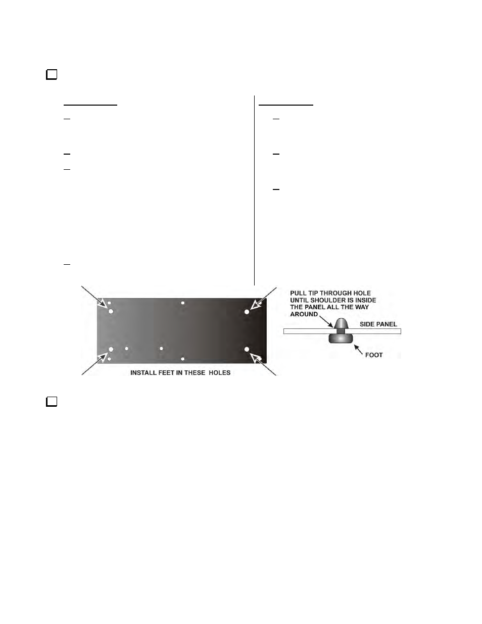
Install the four rubber side feet in the holes in the right side panel as shown in Figure 21. Two suggested
procedures for doing this are as follows:
Press Method:
Wet the tip of the foot with a tiny amount of
soap. (Do not use petroleum jelly or oils. They
can deteriorate the rubber over time).
Place the foot, tip up, on a solid work surface.
Position the panel with the outside (fully painted
side) toward the foot with the hole in the panel
against the tip and press down. The tip should
slip through the hole without further help. If
necessary, grip the tip and pull with your long-
nose pliers, working it from side to side until the
shoulder opens against the inside of the panel.
Do not use excessive force. You can tear the
foot apart.
Wipe any excess soap off of the panel or foot.
Twist Method:
Press the foot against the outside (fully
painted side) of the panel so the tip is in
the hole at an angle.
While pressing the tip into the hole, twist
the foot so the edge of the tip grabs the
inside edge of the hole.
Continue pressing and twisting until the
tip is fully inside the panel all the way
around its circumference. Do not twist
with excessive force. You can tear the
foot apart.
Figure 21. Installing Side Panel Feet.
Position the right side panel against the K3 to verify how it will fit against the RF board. When it is oriented
correctly, the three holes along the bottom edge will line up with the holes in the 2D fasteners on the RF board
and two holes in the side panel will be aligned with the tabs on voltage regulators U12 and U13. The end of the
panel toward the rear will very nearly line up flush with the edge of the RF board. Do not mount the side panel
yet, but note which corner of the panel is in the upper rear corner. You’ll work with this corner in the next step.