Caution – Elecraft K3 Assembly Manual User Manual
Page 23
22
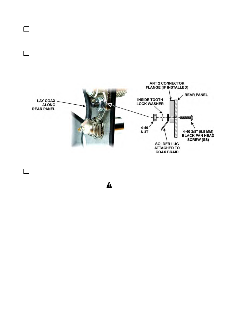
Thread the BNC/TMP cable through the AUX RF connector hole from the outside, lining up the flat on the
threaded section of the connector with the flat at the top of the hole. Slide the lock washer and nut onto the
cable. Fold the solder lug on the braid down against the coax to fit through the back panel hole, the lock washer
and the nut. Thread the nut onto the connector and tighten it (see Figure 20).
Mount the solder lug attached to the braid as shown in Figure 20, using a 4-40 3/8” (9.5mm) black pan head
screw (SS), #4 inside tooth lock washer and 4-40 nut. If you have the KAT3 option, there will be a shorter screw
holding the connector flange. Replace it with the 3/8” (9.5 mm) screw. If you do not have a KAT3, there will be
no connector in the ANT2 hole. In that case, the solder lug is directly against the unpainted inside surface of the
rear panel.
Figure 20. Installing the AUX RF Connector.
Carefully insulate the metal TMP connector, covering all of the metal parts with electrical tape or other
suitable material that you can remove easily later.
CAUTION
Later you will apply power to do preliminary testing and calibration before the KRX3 Subreceiver is
installed. Failure to insulate the TMP connector as described above may result in short circuits and
extensive damage to your K3 if it touches a component, solder pad or other exposed circuit points.