Elecraft K3 Assembly Manual User Manual
Page 62
61
Locate the rear bottom cover section. This cover has eight rectangular slots cut in it. Like the front section,
bare metal is exposed in some areas on the inside surface. The bare metal ensures good electrical contact with
the other cabinet parts and good thermal contact with the heat sinks for Q2, Q4 and Q5 on the LPA circuit
board.
Check the inside surface of the bottom cover for any masking tape that may have been left from the
painting process. If found, peel it off. Two of the screw holes inside bottom cover section B have not had the
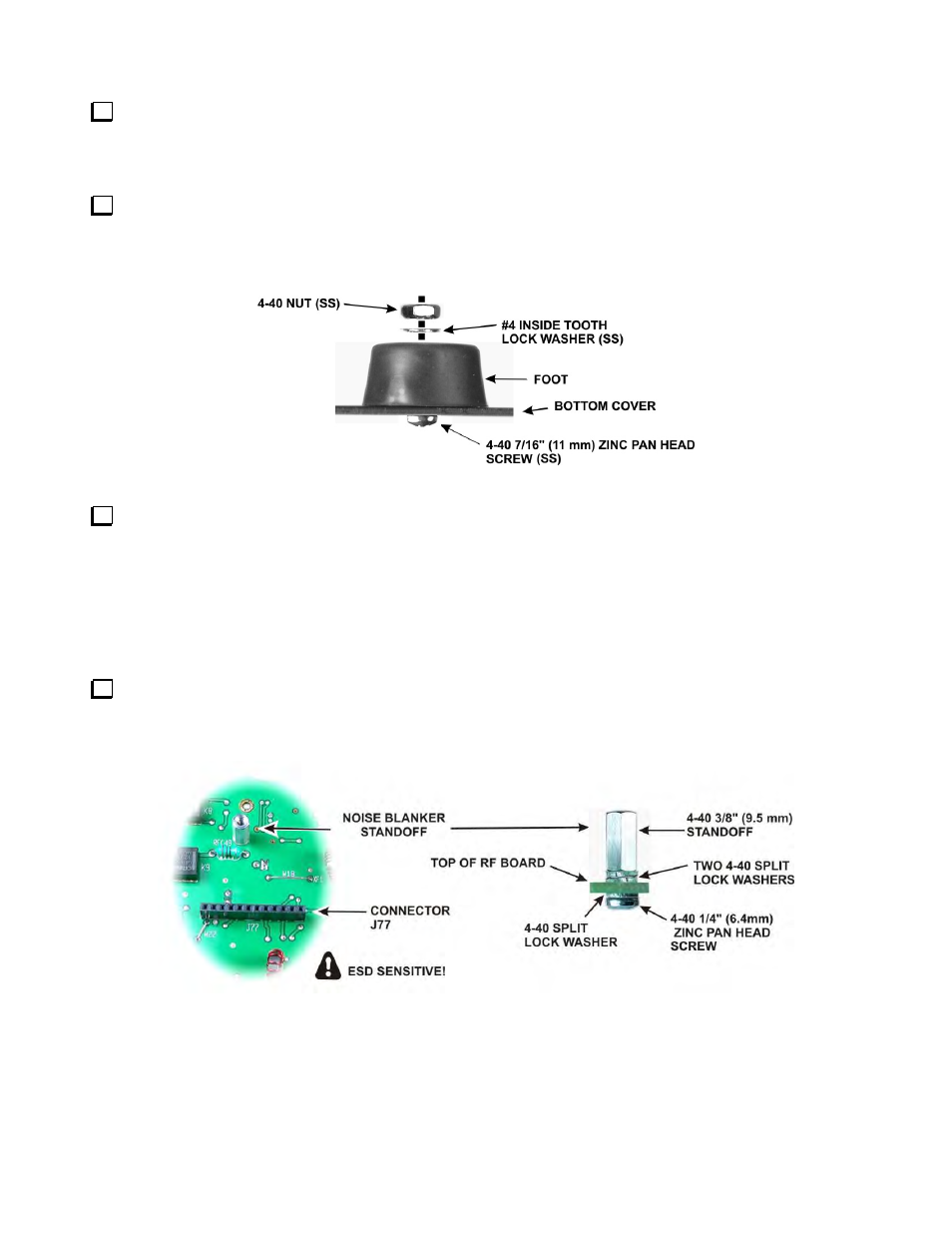
paint removed from them. These are the mounting holes for the two rear feet. Attach each foot as shown in
Figure 85. Note that these screws are also installed with their heads on the inside surface.
Figure 85. Installing Rear Feet.
Set both bottom covers aside in a safe place. They will be mounted on the K3 later.
KNB3 Noise Blanker Description
The KNB3 is one of two noise blanker systems in the K3. It is a narrow I.F. pulse blanker that plugs into the RF
board. See Theory of Operation, Noise Blanker in the K3 Owner’s Manual for more information
KNB3 Installation Procedure
Install the standoff for the noise blanker as shown in Figure 86. The location of J77 is to the left of crystal
filter position FL5 on the RF board. Be sure to put two split lock washers between the standoff and the RF board
as shown.
Figure 86. Installing Noise Blanker Standoff.