System board v1.1 connectors – Dell PowerEdge C8000 User Manual
Page 364
364
Jumpers and Connectors
System Board V1.1 Connectors
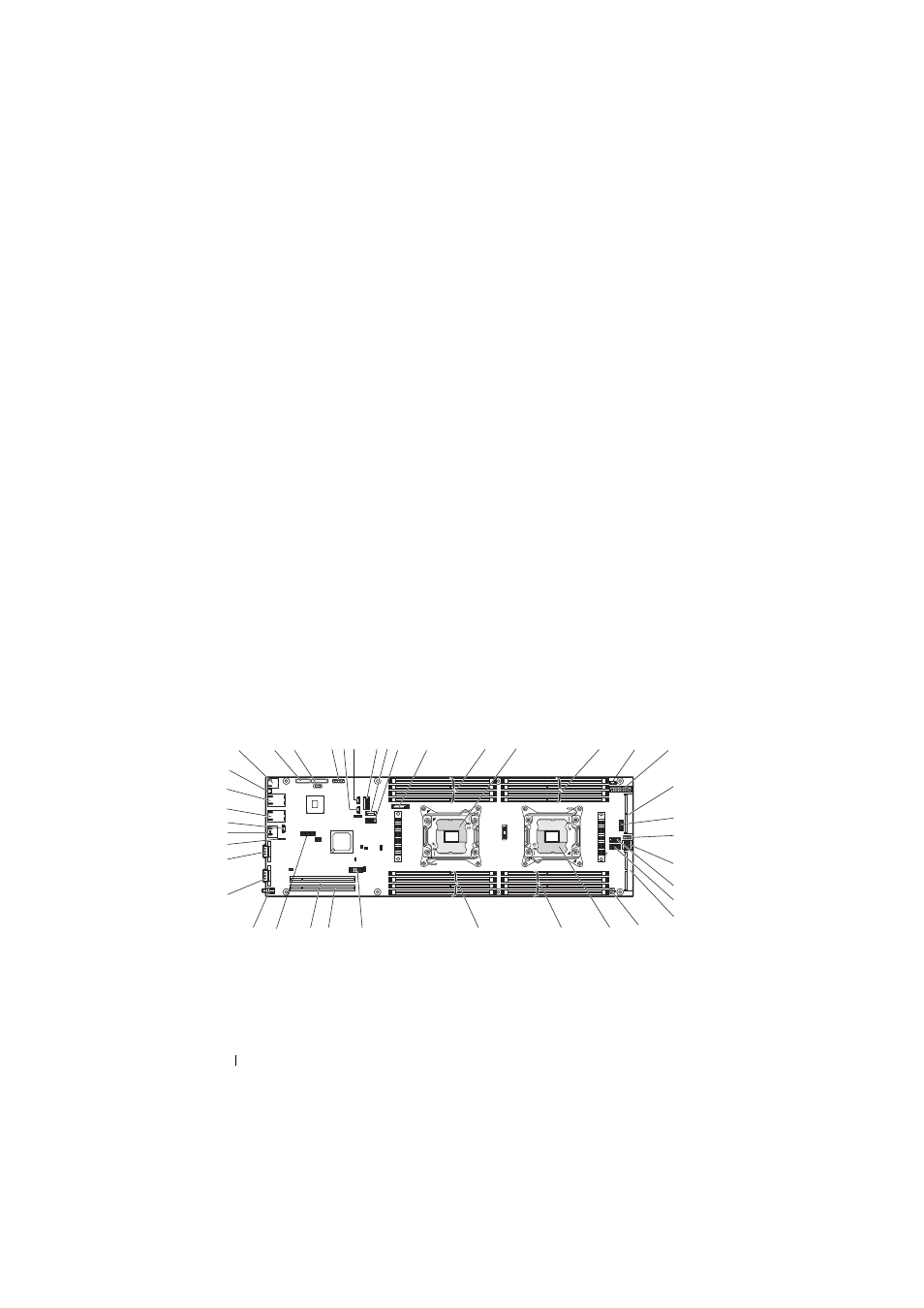
Figure 5-5. System Board V1.1 Connectors
15
internal serial connector
16
front panel connector 1
17
PCIe x16 slot 4 (back GPGPU)
18
CPU2 socket
19
DIMM sockets for CPU2
DIMMB3 socket
DIMMB4 socket
DIMMB7 socket
DIMMB3 socket
20
DIMM sockets for CPU1
DIMMA1 socket
DIMMA2 socket
DIMMA5 socket
DIMMA6 socket
21
LAN LED connector
22
PCIe x16 slot 1
23
PCIe x16 slot 2
24
SGPIO connector 1
25
power button/power-on indicator
26
VGA connector
27
serial connector
28
internal BMC serial console
connector
29
BMC management port
30
consolidated BMC cable
connector
31
NIC1 connector (RJ45)
32
NIC0 connector (RJ45)
33
system identification indicator
1
USB connectors (2)
2
PCIe x8 slot 3 (mezzanine slot)
1
2
3
4
7
9
10
11
13
12
15
16
17
18
24
25
26
27
28
29
30
31
32
33
35
36
37
38
39
34
22
19
20
21
23
6
5
14
8
- PowerEdge RAID Controller H700 (200 pages)
- PowerEdge RAID Controller H700 (178 pages)
- PowerEdge RAID Controller H700 (56 pages)
- PowerVault TL2000 (2 pages)
- PowerVault TL4000 (2 pages)
- PowerVault TL2000 (176 pages)
- PowerVault TL2000 (16 pages)
- PowerVault TL2000 (3 pages)
- PowerVault TL2000 (116 pages)
- PowerVault 130T DLT (Tape Library) (49 pages)
- PowerVault TL2000 (1 page)
- PowerVault 110T DLT VS80 (Tape Drive) (49 pages)
- PowerVault TL2000 (22 pages)
- PowerVault TL4000 (306 pages)
- PowerEdge 800 (2 pages)
- PowerEdge 800 (27 pages)
- PowerEdge 800 (28 pages)
- PowerEdge 800 (58 pages)
- PowerEdge 800 (87 pages)
- PowerEdge 800 (24 pages)
- PowerEdge 800 (82 pages)
- PowerEdge 6400 (86 pages)
- PowerVault 124T (55 pages)
- PowerVault 124T (73 pages)
- PowerVault 124T (65 pages)
- PowerVault 124T (4 pages)
- PowerVault 124T (79 pages)
- PowerVault 124T (2 pages)
- PowerVault 124T (64 pages)
- PowerVault 124T (56 pages)
- PowerVault 124T (66 pages)
- PowerVault 124T (57 pages)
- PowerVault 110T LTO (Tape Drive) (28 pages)
- PowerVault TL4000 (22 pages)
- PowerVault TL4000 (3 pages)
- PowerVault TL4000 (176 pages)
- PowerVault TL4000 (2 pages)
- PowerVault TL4000 (16 pages)
- PowerVault TL4000 (116 pages)
- PowerVault TL4000 (1 page)
- PowerVault TL4000 (66 pages)
- PowerEdge RAID Controller 6i (120 pages)
- PowerEdge RAID Controller 6i (156 pages)
- PowerVault 715N (Rackmount NAS Appliance) (105 pages)
- PowerVault 715N (Rackmount NAS Appliance) (4 pages)