Metrohm 766 IC Sample Processor User Manual
Page 22
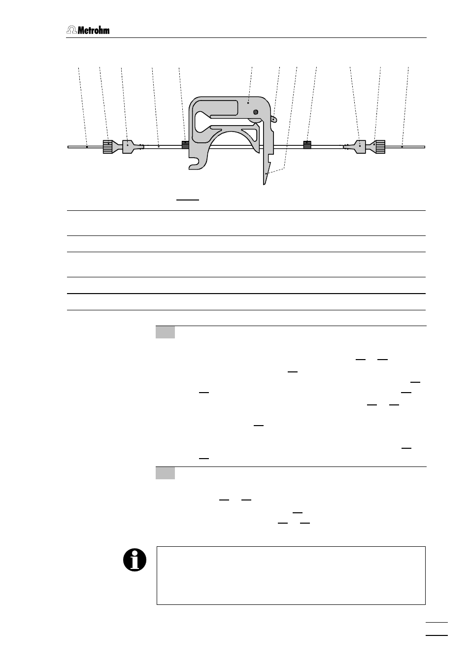
2.3 Attaching the accessories
766 IC Sample Processor
17
88
35
35
10
10
36
36
13
13
15
15
36
36
35
35
18
18
17
17
34
34
66
Fig. 9: Installing the pump tubing
66
PEEK compression fitting
(6.2744.010)
17
17
Snap-action lever
88
PEEK capillary (6.1831.050)
18
18
PEEK capillary (6.1831.060)
10
10
Pump tubing (6.1826.040)
34
34
PEEK compression fitting
(6.2744.010)
13
13
Tubing cartridge (6.2755.000)
35
35
Coupling (6.2744.030)
15
15
Contact pressure lever
36
36
Stopper (black-black)
3 Connection pump tubing – injection valve
•
At the 733 IC Separation Center, loosen the rotary nipple
screwed onto the interior side of connection 22
22 or 28
28.
•
Take PTFE suction tubing 84
84 (see Fig. 14 and Fig. 15 of the
732/733 Instructions for Use) completely out of connection 22
22
or 28
28 and unscrew from connection "1" of injection valve 66
66.
•
Pull the PEEK capillary 18
18 through the opening 22
22 or 28
28 of
the 733 IC Separation Center and screw onto connection "1"
of injection valve 66
66 using a 6.2744.010 PEEK compression
fitting.
•
Retighten rotary nipple on the interior side of connection 22
22
or 28
28 to fix the capillary 18
18.
4 Tubing connection injection valve – waste
•
Insert 6.2744.020 coupling (from 733 accessories) into con-
nection 21
21 or 27
27 of the 733 IC Separation Center.
•
Screw PTFE suction tubing 84
84 onto the 6.2744.020 coupling
attached to connection 21
21 or 27
27 and lead it into the waste
container.
In the case of the 733.0020 IC Separation Center with two injection
valves, it is possible to fill both sample loops from the same 766 IC
Sample Processor. For this, connection "1" of valve A (outlet of the
sample loop) must be connected to connection "2" of valve B (inlet of
the sample loop) using a 6.1803.040 PEEK capillary (15 cm).