Peak detect, Configuration – Rockwell Automation 20D PowerFlex 700S AC Drives with Phase II Control Reference Manual User Manual
Page 79
Rockwell Automation Publication PFLEX-RM003E-EN-E - January 2011
79
Detailed Drive Operation Chapter 1
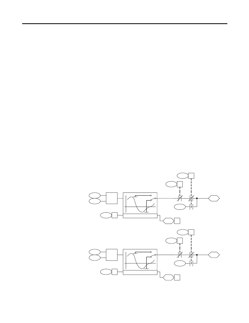
Peak Detect
There are two peak detectors that can be used to detect the peak for a parameter
value.
Configuration:
• Link parameter 212 [PkDtct1 In DInt] or 213 [PkDtct1 In Real] to the
parameter for which you want to detect a peak value, depending on the
data type.
• To detect positive peak values, set parameter 210 [PeakDtct Ctrl In], bit 2
“Peak1SelHigh” = 1. To detect negative peak values, set parameter 210
[PeakDtct Ctrl In], bit 2 “Peak1SelHigh” = 0.
• The peak value is contained in parameter 215 [PeakDetect1 Out].
• To reset the output of the peak detector, toggle on then off parameter 210
[PeakDtct Ctrl In], bit 0 “Peak 1 Set”. The output will match the value in
parameter 214 [PeakDtct1 Preset], which is a default of 0.
• To hold the output of the peak detector at the present value, set parameter
210 [PeakDtct Ctrl In], bit 1 “Peak 1 Hold” = 1.
The change bit, parameter 211 [PeakDtct Status], bit 0 “Peak 1 Chng” is set to
“1” for one scan if the peak detect value changes, otherwise the change bit is set to
“0”. The change bit is also set to “0” if the detector is in Set or Hold mode.
214
212
213
210
2
PeakDtct Status
(Peak 1 Chng)
PkDtct1 In Real
PkDtct1 In DInt
PeakDtct Ctrl In
(Peak1SelHigh)
PeakDtct1 Preset
PeakDetect1 Out
PeakDtct Ctrl In
(Peak 1 Hold)
Σ
PeakDtct Ctrl In
(Peak 1 Set)
211
0
210
1
210
0
215
Peak Detect
218
216
217
210
6
PeakDtct Status
(Peak 2 Chng)
PkDtct2 In Real
PkDtct2 In DInt
PeakDtct Ctrl In
(Peak2SelHigh)
PeakDtct2 Preset
PeakDetect2 Out
PeakDtct Ctrl In
(Peak 2 Hold)
Σ
PeakDtct Ctrl In
(Peak 2 Set)
211
1
210
5
210
4
219
Peak Detect