Bus regulator/braking configuration – Rockwell Automation 20D PowerFlex 700S AC Drives with Phase II Control Reference Manual User Manual
Page 23
Rockwell Automation Publication PFLEX-RM003E-EN-E - January 2011
23
Detailed Drive Operation Chapter 1
Dynamic braking uses a 7th insulated gate bipolar transistor (IGBT) and braking
resistor to dissipate regenerative energy. The drive switches the 7th IGBT on and
off to keep the DC bus voltage at or below the DC bus voltage reference.
Parameters in the PowerFlex 700S drive specify whether the resistor is an internal
or external resistor. When an external resistor is used, you can enter the resistance
value in parameter 544 [External DB Res]. This value can then be used to
determine the power applied to the resistor and calculate its temperature for
resistor protection. Only resistors specifically designed for pulse and high energy
dissipation (dynamic braking) should be used.
The PowerFlex 700S drive allows you to select bus regulation, dynamic braking,
or a combination of bus regulation and dynamic braking.
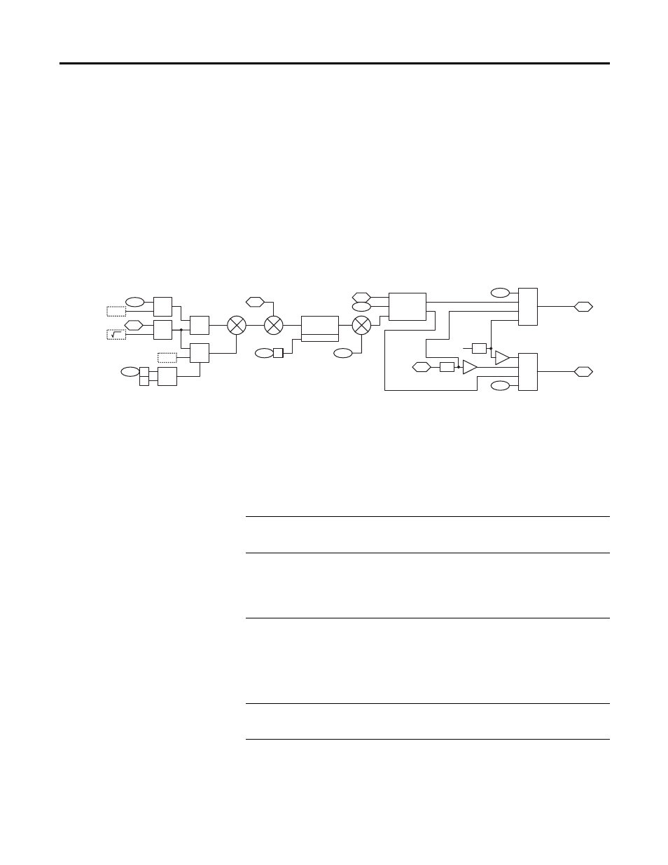
Bus Regulator/Braking Configuration
Parameter 414 [Brake/Bus Cnfg] determines the configuration of bus regulation
and dynamic braking. Parameter 414 is broken down into the following bits:
Power
Limit Calc
Bus Volt
Regulator
Limit
401
306
128
127
300
Min
Max
353
125
126
Motor Spd Fdbk
DC Bus Voltage
Rated Volts
Mtring Power Lim
Regen Power Lim
Torque Pos Limit
Torque Neg Limit
Iq Actual Lim
Brake/Bus Cnfg
(Bus Reg En)
123
124
Torque PosLim Actl
Torque NegLim Actl
414
00
02
&
X
X
415
Brake/Bus Cnfg
(Brake Enable )
(BusRef High)
BusReg/Brake
Ref
X
/
-1
-1
Cur Lim MC
Flux
Flux
414
03
+
+
+
-
+
+
100
2
0.045
from
8H2
Bit 0 “Brake Enable”
When this bit is set to 1, it enables the internal brake transistor (7th IGBT). When this bit is set to
0, the internal brake transistor is disabled.
Bit 1 “Brake Extern”
When this bit is set to 1, it configures the brake operation for an external resistor. In this case, the
external brake resistor protection is based on the peak watts entered into parameter 416 [Brake
PulseWatts] and the continuous watts entered in parameter 417 [Brake Watts]. When this bit is
set to 0, it configures the brake operation for an internal resistor. In this case, parameters 416
[Brake PulseWatts] and 417 [Brake Watts] are not active.
Bit 2 “Bus Ref High”
This bit configures whether bus regulation or dynamic braking turns on first. This bit is only active
when parameter 414 [Brake/Bus Cnfg] bits 0 and 3 are both set to 1. When this bit is set to 1, the
dynamic braking turns on first (at the DC bus voltage set by parameter 415 [Bus Reg/Brake Ref]),
and then the bus regulator turns on if the DC bus voltage continues to rise (at the DC bus voltage
set by 415 [Bus Reg/Brake Ref] plus 4.5%). When this bit is set to 0 the bus regulator turns on
first (at the DC bus voltage set by 415 [Bus Reg/Brake Ref]) and then the dynamic braking turns on
when there are any transients above 415 [Bus Reg/Brake Ref].
Bit 3 “Bus Reg En”
When this bit is set to 1, bus regulation is enabled. When this bit is set to 0, bus regulation is
disabled.