Rockwell Automation 20D PowerFlex 700S AC Drives with Phase II Control Reference Manual User Manual
Page 203
Rockwell Automation Publication PFLEX-RM003E-EN-E - January 2011
203
Detailed Drive Operation Chapter 1
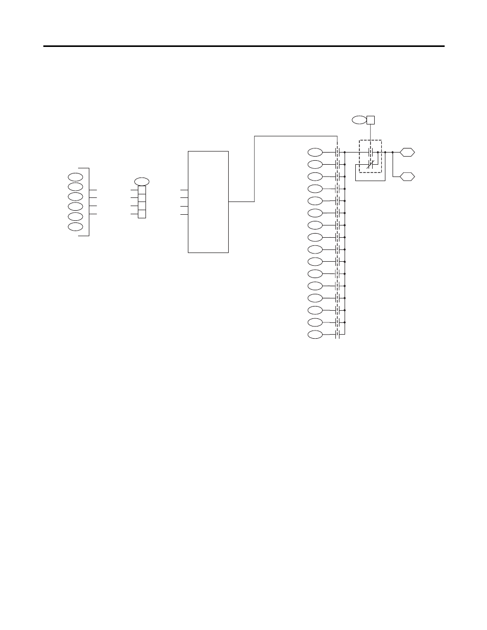
Using Digital Inputs and the Selector Switches to Configure Preset Speeds:
The digital inputs can be used to configure up to 16 preset speeds using the
Selector Switches function.
Example Digital Input and Selector Switch Configuration:
In this example, three digital inputs are used to control the status of bits 1 “Sel
Swtch 00”…3 “Sel Swtch 02” of parameter 1022 [Sel Switch Ctrl] to then select
one of eight preset speeds configured in parameters 1029…1036. The binary
coded decimal (BCD) output of bits 1 “Sel Swtch 00”…3 “Sel Swtch 02” of
parameter 1022 are or’d together to select the desired parameter and preset speed.
• Set parameter 826 [Dig In2 Sel] to 34 “UserGen Sel0”. When digital input
2 is energized, bit 1 “Sel Swtch 00” of parameter 1022 is set high.
• Set parameter 827 [Dig In3 Sel] to 35 “UserGen Sel1”. When digital input
3 is energized, bit 2 “Sel Swtch 01” of parameter 1022 is set high.
• Set parameter 828 [Dig In4 Sel] to 36 “UserGen Sel2”. When digital input
2 is energized, bit 3 “Sel Swtch 02” of parameter 1022 is set high.
• Set bit 1 “Sel Switches” of Par 1000 [UserFunct Enable] to “1” (enables the
Selector Switch user function).
• Set bit 0 “SSW DataPass” of Par 1022 [Sel Switch Ctrl] to “1” (enables the
passing of the data from the selected parameter to Par 1045 [SelSwtch
RealOut] and 1046 [SelSwtch DIntOut]).
1029
1030
1031
0
1
2
3
4
5
6
1032
1034
1035
SelSwtch In01
(Real)
7
8
9
10
1036
1037
1038
1039
1040
12
13
14
15
11
1033
1041
1042
1043
1044
1045
1046
SelSwtch DIntOut
(Integer )
SelSwtch RealOut
(Real)
SelSwtch In02
(Real)
SelSwtch In03
(Real)
SelSwtch In04
(Real)
SelSwtch In05
(Real)
SelSwtch In06
(Real)
SelSwtch In07
(Real)
SelSwtch In08
(Real)
SelSwtch In09
(Real)
SelSwtch In10
(Real)
SelSwtch In11
(Real)
SelSwtch In12
(Real)
SelSwtch In13
(Real)
SelSwtch In14
(Real)
SelSwtch In15
(Real)
SelSwtch In00
(Real)
with Rounding
1022
00
Sel Swtch Ctrl
Binary Coded
Decimal (BCD)
control that selects
1 of 16 inputs (Pars
1029 – 1044 ) that
provides output to
Par 1045 or Par
1046 . BCD values
of bits 01 – 04 of
Par 1022 are or’d
together to select a
switch. Bit 01 of
1022 is the LSB. A
binary value of
“0000 ” selects Par
1029 . A binary
value of “1111 "
selects Par 1044 .
1022
02
03
Sel Swtch Ctrl
828
Dig In4 Sel
827
Dig In3 Sel
826
Dig In2 Sel
“UserGen Sel0”
“Sel Switch 00”
“Sel Switch 01”
“Sel Switch 02”
01
“UserGen Sel 1”
“UserGen Sel2”
825
Dig In1 Sel
829
Dig In5 Sel
830
Dig In6 Sel
04
“Sel Switch 03”
“UserGen Sel3”