Speed regulator tuning, Speed regulator output filter, Basic tuning with a gear box or belt – Rockwell Automation 20D PowerFlex 700S AC Drives with Phase II Control Reference Manual User Manual
Page 158
158
Rockwell Automation Publication PFLEX-RM003E-EN-E - January 2011
Chapter 1 Detailed Drive Operation
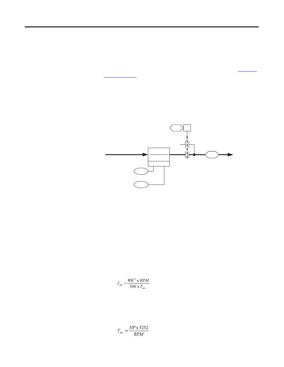
Speed Regulator Output Filter
Once the proportional and integrator blocks are summed, the torque reference
goes through a lead/lag filter, tuned by parameters 95 [SRegOut FiltGain] and 96
[SReg Out Filt BW]. For more information on lead/lag filters refer to
Parameter 157 [Logic Ctrl State] bit 8 “Spd Reg En” indicates when the speed
regulator is enabled. When bit 8 “Spd Reg En” is enabled, the speed regulator
output is allowed to pass to the torque control loop.
Parameter 302 [Spd Reg PI Out] contains the filtered, limited torque reference
that was generated by the speed regulator.
Speed Regulator Tuning
Basic Tuning with a Gear Box or Belt
This section provides guidelines for basic tuning of the speed loop when the
motor is coupled to the load through a gear box.
1.
Identify motor and system inertia (in seconds). The motor inertia can be
determined by performing an inertia test with the motor uncoupled from
the load, or the motor inertia in seconds can be calculated using the
following formula:
where WK
2
is the inertia in lbft
2
, RPM is the base motor speed of the
motor, and T
acc
is the rated torque of the motor in lbft. T
acc
can be
calculated using the following formula:
95
96
157
08
0
302
0
1
SRegOut FiltGain
SReg Out Filt BW
Logic Ctrl State
(Spd Reg En)
Spd Reg PI Out
to Torque Control
[4A1]
Lead Lag
(kn * s)+ wn
s + wn