Speed reference filter, Speed reference scaling, Speed trim 1 – Rockwell Automation 20D PowerFlex 700S AC Drives with Phase II Control Reference Manual User Manual
Page 151
Rockwell Automation Publication PFLEX-RM003E-EN-E - January 2011
151
Detailed Drive Operation Chapter 1
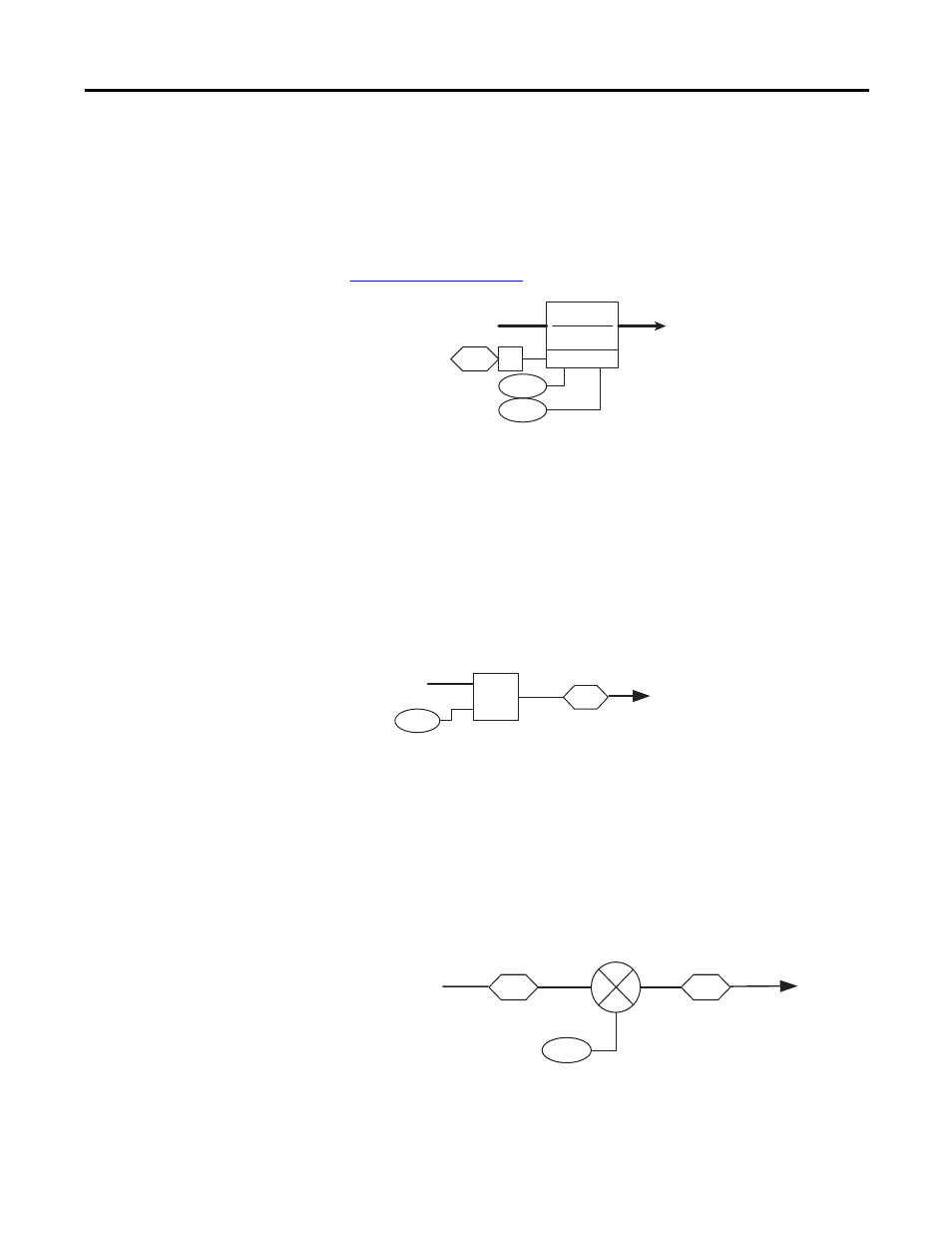
Speed Reference Filter
A lead-lag filter for the selected speed reference can be turned on by setting
parameter 153 [Control Options] bit 1 “SRef LdLg En” = “1”. Parameter 35
[SpdRef Filt Gain] sets the gain for the filter and parameter 36 [SpdRef Filt BW]
sets the bandwidth for the filter. For more information on lead/lag filters see
Speed Reference Scaling
The speed reference value up to this point is multiplied by the scaling parameter
38 [Speed Ref Scale]. [Speed Ref Scale] is applied to all of the selected speed
references, as opposed to the specific scaling parameters for speed reference 1 and
2. [Speed Ref Scale] is a linkable parameter. This allows the speed reference value
to be scaled “dynamically” with an input signal if desired. An example would be
to have an analog input linked to the scale parameter. The speed reference and the
scale would then affect the value sent to the speed regulator.
Speed Trim 1
At this point in the speed reference control loop, parameter 21 [Speed Trim 1] is
added to the speed reference. [Speed Trim 1] can be used as a trim to the speed
reference. For example, [Speed Trim 1] can be linked to parameter 180 [PI
Output], which is the output of the Process PI loop. The resulting parameter 47
[SpdRef + SpdTrm1] is sent into the speed regulator loop.
153
01
35
36
From Ramp
To Speed
Reference Scale
Control Options
(SRef Filt En)
SpdRef Filt Gain
SpdRef Filt BW
Lead Lag
(kn * s)+ wn
s + wn
X
38
46
Scaled Spd Ref
Speed Ref Scale
to Speed Trim
from Speed
Ref Filter
21
47
46
Scaled Spd Ref
from Speed
Ref Scale
SpdRef + SpdTrm1
to Speed
Regulator
Speed Trim 1
+
+