Inertia adaption – Rockwell Automation 20D PowerFlex 700S AC Drives with Phase II Control Reference Manual User Manual
Page 61
Rockwell Automation Publication PFLEX-RM003E-EN-E - January 2011
61
Detailed Drive Operation Chapter 1
Controlling the Indexer from a Network or DriveLogix:
Toggle parameter 740 [Position Control] bit 12 “BscIndx Step” to index forward.
Toggle 740 [Position Control] bit 15 “BscIndxStpRv” to index reverse.
[Position Control] can be controlled by from a network by using a Datalink.
Refer to
for details.
[Position Control] can be controlled from DriveLogix by linking it to one of the
FromDriveLogix words (parameters 602 to 622). See the
DriveLogix 5730
Controller User Manual, publication
Inertia Adaption
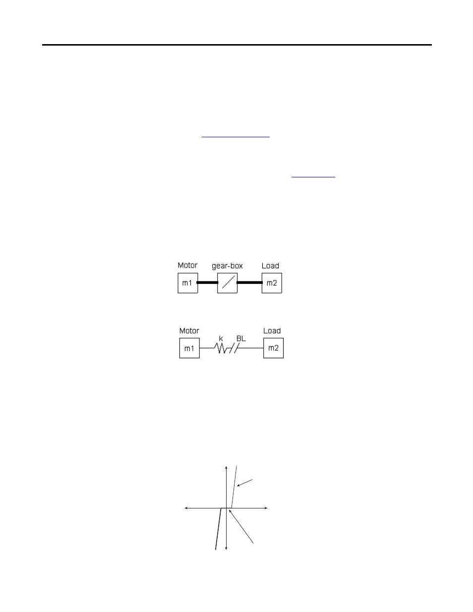
Inertia adaption is used to compensate for lost motion, which occurs when a gear
box and/or “springy” coupling is present. Inertia adaption can allow the user to
increase the speed regulator bandwidth by up to four (4) times.
For example, a motor connected to a gearbox is shown:
This gearbox can be represented by a spring (k) and gear back lash (BL):
When the speed of the motor increases, there is a period of time (represented by
Δ
x) before the teeth of the gearbox engage. After that time, there will be some
twisting (like a spring) in the shaft after the teeth of the gearbox engage. This lost
motion causes mechanical instability and limits how high the speed regulator
bandwidth can be set without causing instability. Inertia adaption detects the lost
motion and a higher speed regulator bandwidth can be achieved without
instability.
s
lope d
u
e to
s
pringy
n
a
t
u
re (k) of
s
h
a
ft
s
a
fter ge
a
r
b
ox teeth
eng
a
ge
ba
ckl
as
h (BL)
b
efore ge
a
r
b
ox
teeth eng
a
ge
Δ
x
f