Inertia compensation, Configuration – Rockwell Automation 20D PowerFlex 700S AC Drives with Phase II Control Reference Manual User Manual
Page 62
62
Rockwell Automation Publication PFLEX-RM003E-EN-E - January 2011
Chapter 1 Detailed Drive Operation
Configuration
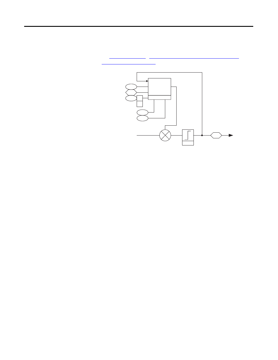
See
Advanced Tuning for the Speed Regulator with
for details on using inertia adaption.
Inertia Compensation
During speed changes, a certain level of torque is required due to load inertia.
That level of torque is above the torque used to run at constant speed. Inertia
compensation calculates that torque based on the acceleration or deceleration
rate. Then that acceleration or deceleration torque can be fed forward into the
torque control, making for smoother accels and decels, especially with high
inertia loads.
Parameter 56 [Inertia SpeedRef ] is linked to parameter 43 [Ramped Spd Ref ].
This becomes the speed reference that the inertia compensation block uses to
calculate the acceleration or deceleration rate, also known as the derivative of
speed with respect to time.
Inertia compensation is enabled by turning on parameter 151 [Logic Command],
bit 10 “Inertia Comp”.
Parameter 9 [Total Inertia] is calculated during the autotune and is used along
with the calculated acceleration or deceleration rate to calculate the torque adder.
Parameter 57 [InertiaAccelGain] determines the gain for the inertia
compensation during acceleration. A gain of 1 results in 100% compensation.
Parameter 58 [InertiaDecelGain] determines the gain for the inertia
compensation during deceleration.
Parameter 60 [DeltaSpeedScale] is a multiplier for the torque output of the
inertia compensation block. It is used in center wind and center unwind
applications to compensate for diameter build-up.
Limit
303
Motor Torque Ref
Inertia
Adaptation
9
300
Total Inertia
Motor Spd Fdbk
132
00
01
Inert Adapt Sel
(Inrtia Adapt )
(Load Est )
133
134
Inert Adapt BW
Inert Adapt Gain
-
+
From Spd /Torque
Mode Selection
To Current
Control
Torque Limits