Proportional gain – Rockwell Automation 20D PowerFlex 700S AC Drives with Phase II Control Reference Manual User Manual
Page 156
156
Rockwell Automation Publication PFLEX-RM003E-EN-E - January 2011
Chapter 1 Detailed Drive Operation
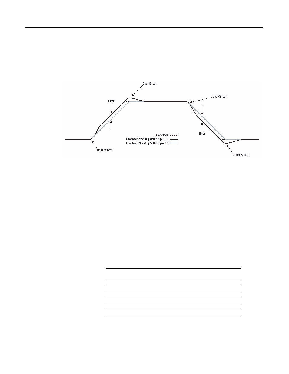
However, it will exhibit some over-shoot and under-shoot. Increasing the value of
[SpdReg AntiBckup] decreases the over-shoot and under-shoot, which is
desirable where back-up cannot be tolerated. However, this tends to increase the
following error: This parameter has no affect on the drive's response to load
changes. The recommended setting is 0.1 to 0.5. The following is an example of
how the anti-backup affects the speed regulator’s response.
Proportional Gain
The filtered speed error (after the servo lock is added and the anti-backup is
subtracted) is sent to the proportional gain block. The proportional gain
determines how much of a speed error occurs during a load transient.
Parameter 81 [Spd Reg P Gain] sets the proportional gain of the speed regulator.
It's value is automatically calculated based on the bandwidth setting in parameter
90 [Spd Reg BW] and parameter 9 [Total Inertia]. Proportional gain may be
manually adjusted by setting [Spd Reg BW] to a value of zero. Units are (per unit
torque) / (per unit speed). For example, when parameter 81 [Spd Reg P Gain] is
20, the proportional gain block will output 20% motor rated torque for every 1%
error of motor rated speed.
The maximum value for Par 81 [Spd Reg P Gain] = Par 90 [Spd Reg BW] x Par 9
[Total Inertia].
Max. Speed Regulator
Bandwidth (Par 90)
Total Inertia (Par 9)
Max. Speed Regulator
Proportional Gain (Par 81)
475 (0.5 ms)
x
0.01
=
4.75
650 (0.25 ms)
x
0.01
=
6.50
30 (sensorless mode)
x
0.01
=
0.03
475 (0.5 ms)
x
2.0
=
950
650 (0.25 ms)
x
2.0
=
1300
30 (sensorless mode)
x
2.0
=
60