3ć26, 4 data table bit assignments – Rockwell Automation 1772-LP3 PLC - 2/30 Programmable Controller Programming and Operations Manual User Manual
Page 53
Data Table
Chapter 3
3Ć26
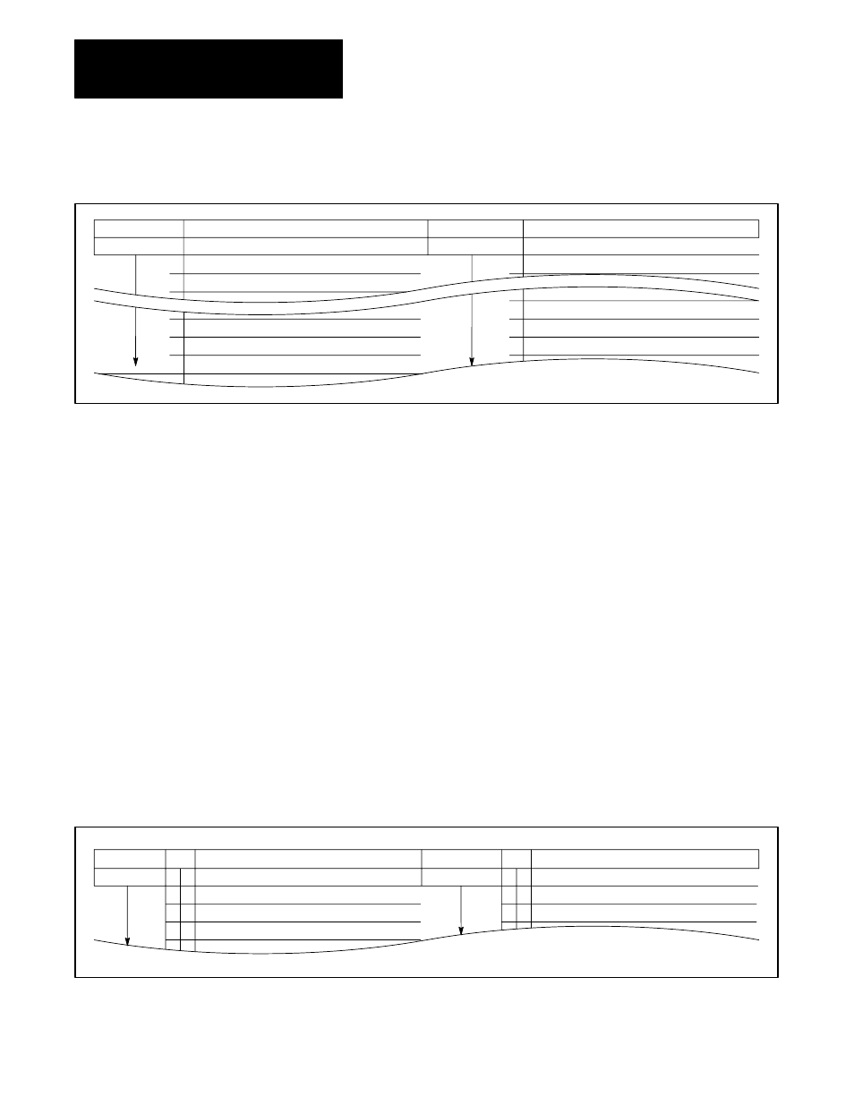
Figure 3.10
Example of Data Table Word Assignments
0
1
2
5
6
7
0
1
4
5
6
WORD ADDR
DESCRIPTION
WORD ADDR
DESCRIPTION
20
Master cycle time, AC
Drillhead #1, dwell time, AC
No. of reject parts, AC
No. of passes, AC
30
Master cycle time, PR
Drillhead #1, dwell time, PR
No. of reject parts, PR
No. of passes, PR
This form can be used to log the function of input, output and storage bits.
Similar to the word assignment sheet, the bit assignment sheet is divided
into two 2-word columns. The words can be numbered consecutively, or
the right-hand column can be numbered 1008 greater than the left-hand
column for the convenient logging of input, output and/or storage bits
having the same I/O group number. The bit numbers are prenumbered,
00-17.
For example, a portion of the data table bit assignment sheet is shown
in Figure 3.11. It illustrates logging the input devices associated with
I/O group 2 and the storage of the corresponding storage word 012
(complement of word 112). Word address 012 and 112 have been entered
into corresponding word address boxes in the left- and right-hand columns,
respectively. The 3-, 4- or 5-digit word address is entered once for all 16
bits.
Figure 3.11
Example of Data Table Bit Assignments
0
0
0
0
0
1
2
3
0
0
0
0
1
2
WORD
BIT
DESCRIPTION
WORD
BIT
DESCRIPTION
012
112
CR1, run auto (sto.)
CR2, part preset latch (sto.)
CR3, op. compl. (sto.)
LS1 Forward overtravel
PRS1 Part detect
PB1 Up-jog
3.4.4
Data Table Bit Assignments