1 upćcounter instruction – Rockwell Automation 1772-LP3 PLC - 2/30 Programmable Controller Programming and Operations Manual User Manual
Page 107
Timer and Counter Instructions
Chapter 5
5Ć9
Bit 14 is the overflow/underflow bit. It is set to one when the AC value
of the CTU exceeds 999 or the AC value of the CTD goes below 000.
Bit 15 (the Done bit) is set to one when a count has been reached or
exceeded, that is, when the AC value is
≥
PR value.
Bit 16 is the enabled bit for a CTD instruction. It is set on when rung
conditions are true.
Bit 17 is the enabled bit for a CTU instruction. It is set on when rung
conditions are true.
Counter instructions differ from Timer instructions in that they have no
time base. They count one event each false-to-true transition of the rung.
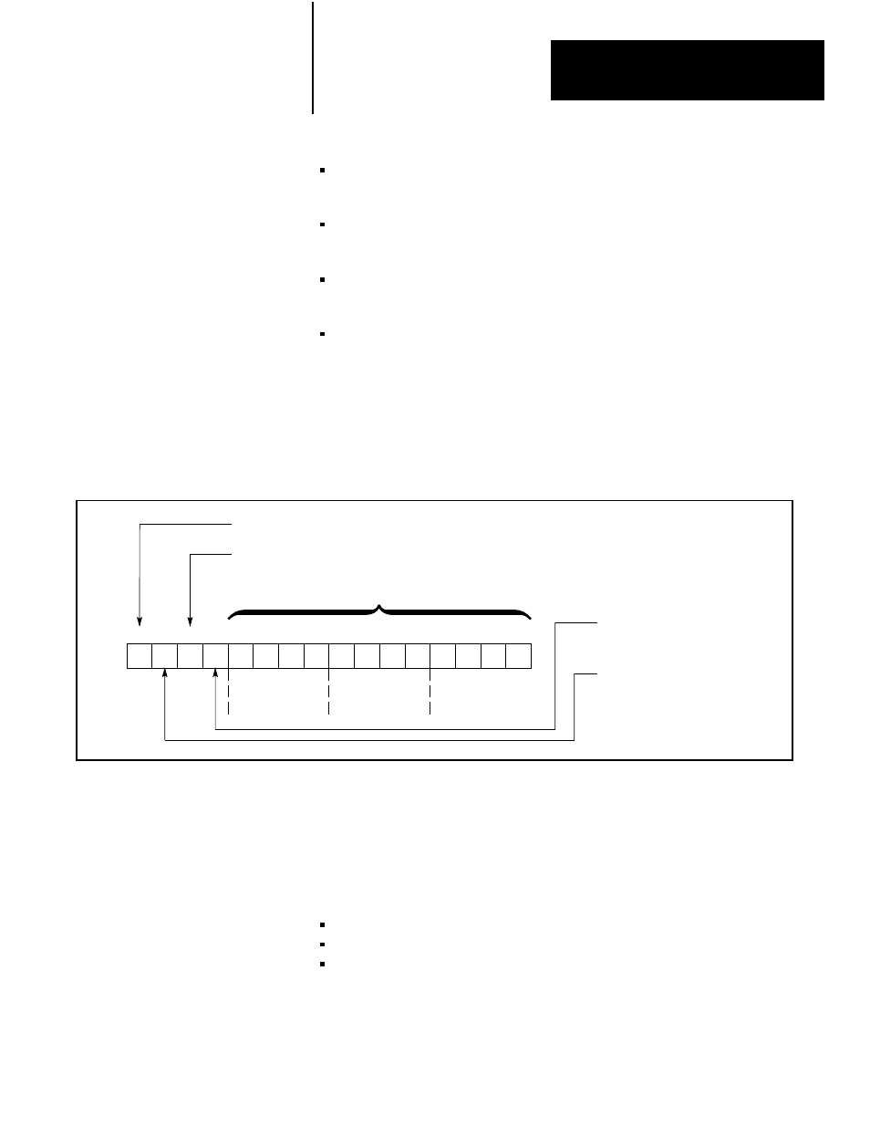
Figure 5.6
Counter Accumulated Value Word
17 16 15 14 13 12 11 10 07 06 05 04 03 02 01 00
Most
Significant
Digit
Middle
Digit
Least
Significant
Digit
Accumulated Value
in BCD Form
Overflow/Underflow Bit Set to 1
When CTU Overflows 999
or CTD Underflows 000.
DownĆCounter Enable Bit
Set to 1
When AC
≥
PR
UpĆCounter Enable Bit
The Up-Counter (CTU) instruction increments its accumulated value for
each false-to-true transition of rung conditions (Figure 5.7). Because only
the false-to-true transition causes a count to be made, rung conditions must
go from true to false and back to true before the next count is registered
(Figure 5.7). The CTU instruction retains its accumulated value when:
Mode select switch is changed to the PROGRAM position
Rung conditions go false
Power outage occurs provided memory backup power is maintained for
RAM memory
Each time the CTU rung goes true, bit 17, the Enabled bit, is set on. When
the accumulated value reaches the preset value, bit 15 is set on. Unlike a
5.2.1
UpĆCounter Instruction