Programming file diagnostic instruction – Rockwell Automation 1772-LP3 PLC - 2/30 Programmable Controller Programming and Operations Manual User Manual
Page 298
File Search and File Diagnostic Instructions
Chapter 17
17Ć6
Programming File Diagnostic Instruction
WARNING: The counter address specified for the File
Diagnostic instruction should be reserved for that instruction.
Do not manipulate the counter preset or accumulated values.
Inadvertent change to these values could result in hazardous or
unpredictable machine operation or a run-time error. Damage to
equipment and/or personal injury could result.
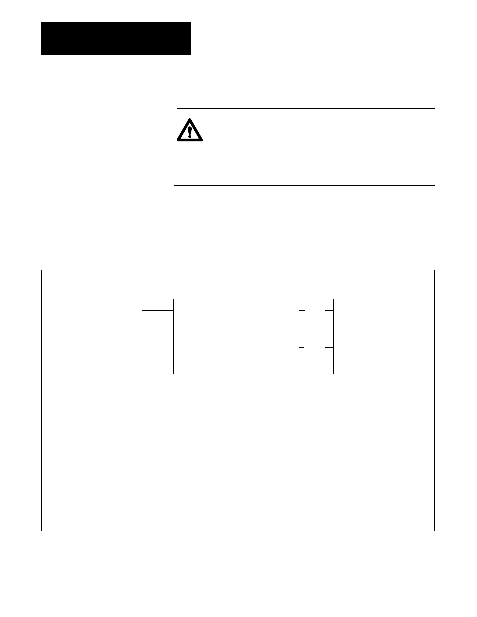
To program a File Diagnostic instruction, press [FILE] 20. A display
represented by Figure 17.5 will appear.
Figure 17.5
FILE DIAGNOSTIC Format
FILE DIAGNOSTIC
COUNTER ADDR: 030
FILE LENGTH: 001
FILE: 110- 110
BASE: 110- 110
ERROR: 010- 012
#0001 AT 00000/00
030
(EN)
17
Numbers shown are default values. Bold numbers must be replaced by userĆentered values. The number of default address digits
initially displayed Ċ 3, 4, or 5 Ċ will depend on the size of the data table. Initially displayed default values are governed by the I/O rack
configuration.
COUNTER ADDRESS : Address of the instruction in the accumulated value area of the data table.
FILE LENGTH : Number of words in file (preset value of the counter).
FILE : Starting address of file containing discrepancies between actual and desired I/O states (File R of XOR
instruction).
BASE : Starting address of file containing actual I/O (File A of XOR instruction).
ERROR : The first address of three consecutive words that store the error number and I/O bit address of the
malfunctioning I/O device.
#
: Displayed error number and corresponding I/O bit address.
030
(DN)
15
Figure 17.6 shows the format of Figure 17.5 after the following conditions
are entered. These values are based on the use of the XOR instruction
depicted in Figure 17.4a.