Rockwell Automation 1772-LP3 PLC - 2/30 Programmable Controller Programming and Operations Manual User Manual
Page 247
Shift Register Instructions
Chapter 13
13Ć4
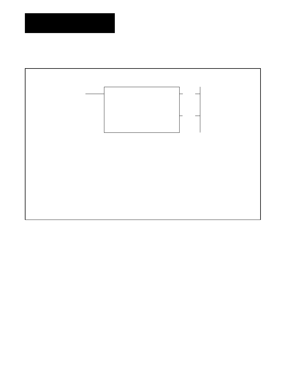
Figure 13.3
SHIFT FILE UP Format
SHIFT FILE UP
COUNTER ADDR: 030
FILE LENGTH: 001
FILE: 110- 110
INPUT ADDR: 010
OUTPUT ADDR: 010
RATE PER SCAN: 001
030
(EN)
17
Numbers shown are default values. Bold numbers must be replaced by userĆentered values. The number of default address digits
initially displayed Ċ 3, 4, or 5 Ċ will depend on the size of the data table. Initially displayed default values are governed by the I/O rack
configuration.
COUNTER ADDRESS : Address of the instruction in the accumulated value area of the data table.
FILE LENGTH : Number of words in file (preset value of the counter).
FILE : Starting word of file.
INPUT ADDRESS : Address of input word.
OUTPUT ADDRESS : Address of output word.
RATE PER SCAN : Number of words operated upon per scan.
030
(DN)
15
Figure 13.4 shows the format of Figure 13.3 after the following conditions
have been entered.
COUNTER ADDR – 200
FILE LENGTH – 064
FILE – File starts and ends at words 400 and 477 respectively
INPUT ADDR – 120
OUTPUT ADDR – 500
RATE PER SCAN – 064
This is the complete mode. A word is shifted into and a word is shifted out
of the file each scan.
The procedure for using the data monitor mode for data entry or monitor is
presented in Chapter 12.