Rockwell Automation 1772-LP3 PLC - 2/30 Programmable Controller Programming and Operations Manual User Manual
Page 250
Shift Register Instructions
Chapter 13
13Ć7
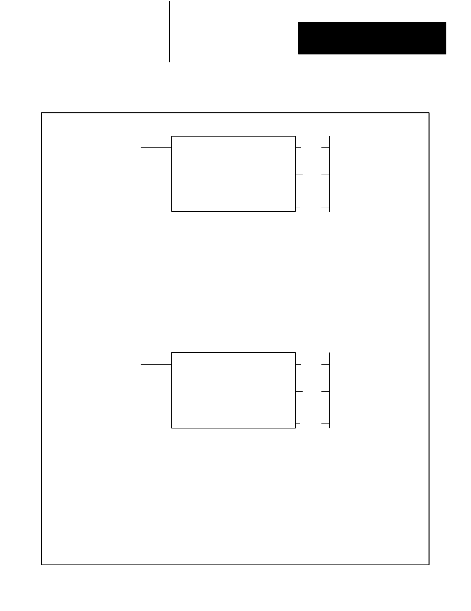
Figure 13.5
Format for FIFO LOAD and FIFO UNLOAD Instructions
FIFO UNLOAD
COUNTER ADDR:
030
FIFO SIZE:
001
NUMBER IN FILE:
000
FILE:
110- 110
INPUT ADDR:
010
INPUT DATA:
0000
030
(EN)
17
Numbers shown are default values. Bold numbers must be replaced by userĆentered values. The number of default address digits
initially displayed Ċ 3, 4, or 5 Ċ will depend on the size of the data table. Initially displayed default values are governed by the I/O rack
configuration.
COUNTER ADDRESS
: Address of the instruction in the accumulated value area of the data table.
FIFO SIZE
: The maximum number of words that the FIFO stack can contain.
NO IN FILE
: Current number of words in the stack.
FILE
: Starting address of the FIFO stack location.
INPUT ADDRESS
: Address of input word outisde the stack.
INPUT DATA
: Current data at input address.
030
(FL)
15
Numbers shown are default values. Bold numbers must be replaced by userĆentered values. The number of default address digits
initially displayed Ċ 3, 4, or 5 Ċ will depend on the size of the data table. Initially displayed default values are governed by the I/O rack
configuration.
COUNTER ADDRESS
: Address of the instruction in the accumulated value area of the data table.
FIFO SIZE
: The maximum number of words that the FIFO stack can contain.
NO IN FILE
: Current number of words in the stack.
FILE
: Starting address of the FIFO stack location.
OUTPUT ADDRESS
: Address of output word outisde the stack.
OUTUT DATA
: Current data at output address.
030
(EM)
14
FIFO LOAD
COUNTER ADDR:
030
FIFO SIZE:
001
NUMBER IN FILE:
000
FILE:
110- 110
OUTPUT ADDR:
010
OUTPUT DATA:
0000
030
(EN)
16
030
(FL)
15
030
(EM)
14