Rockwell Automation 1772-LP3 PLC - 2/30 Programmable Controller Programming and Operations Manual User Manual
Page 186
Block Transfer
Chapter 10
10Ć3
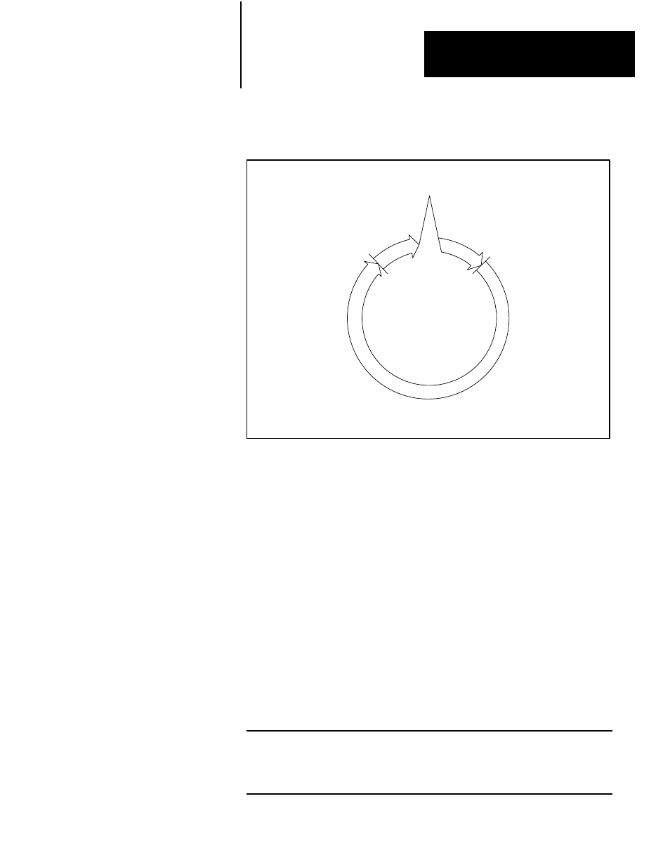
Figure 10.2
Block Transfer Diagram
Request is made in
Program Scan
Transfer is made
in I/O Scan
Output
Scan
Input
Scan
Once the module address is found, the processor locates the address of the
file to which (or from which) the data will be transferred. The file address
is stored in BCD at an address 100
8
above the address containing the
module address. This is done in the same manner that the processor locates
the preset value of a timer in a word address 100
8
above the accumulated
value address. The analogy between block transfer and timer/counter data
and addresses is shown in Table 10.A.
After locating the file address in the timer/counter area of the data table,
the processor then duplicates and transfers the file data consecutively one
word at a time until complete, starting at the selected file address.
At the completion of the transfer, a done bit for the read or write operation
is set in the input image table byte as a signal that a valid transfer has been
completed.
Table 10.A
Timer/Counter Block Transfer Analogy
Address of Accumulated Value
↔
Data Address of Instruction
Accumulated Value in BCD
↔
Module Address in BCD
Address of Preset Value
↔
100
8
Above Data Address
Preset Value in BCD
↔
File Address in BCD