Rockwell Automation 1772-LP3 PLC - 2/30 Programmable Controller Programming and Operations Manual User Manual
Page 30
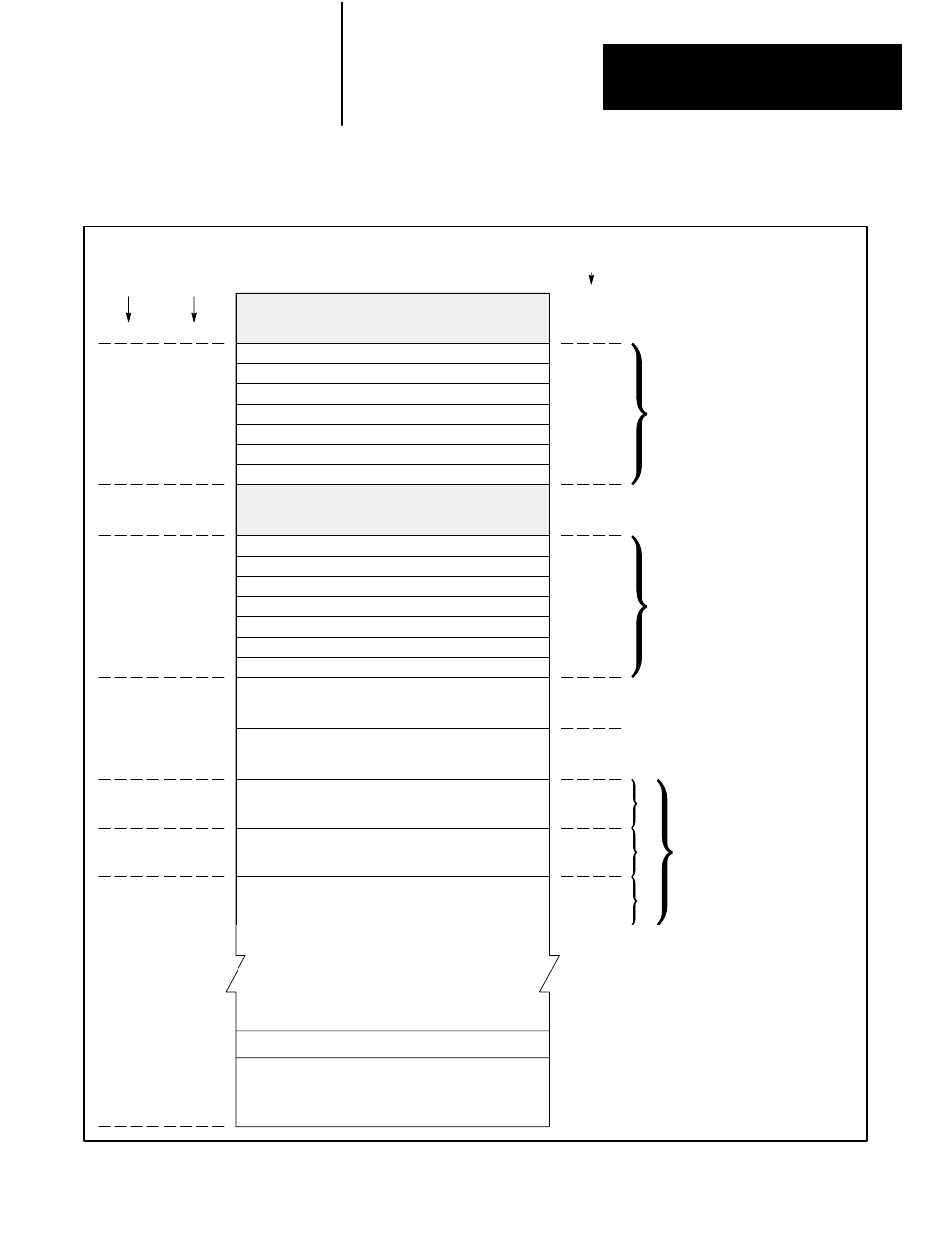
Data Table
Chapter 3
3Ć3
Figure 3.2
PLCĆ2/30 Memory Organization (Expanded Data Table)
User Program Storage
(User Program Begins
After End of Last
Data Table Expansion)
Processor Work Area
No. 1
Processor Work Area
No. 2
Expansion
1
Expansion
2
Expansion
3
(etc.)
Timer/Counter ACC Values or
Internal Storage
Timer/Counter Preset Values or
Internal Storage
Message Storage
3
End of Program
Rack 1ą010Ć017
Rack 2ą020Ć027
1
Rack 3ą030Ć037
Rack 4ą040Ć047
Rack 7ą070Ć077
Rack 6ą060Ć067
Rack 5ą050Ć057
Rack 1ą110Ć117
Rack 2ą120Ć127
2
Rack 3ą130Ć137
Rack 4ą140Ć147
Rack 7ą170Ć177
Rack 6ą160Ć167
Rack 5ą150Ć157
1
027 - Bits in this word are used by the
processor for battery low condition, message
generation, and data highway. Do not put
output modules in rack 2, I/O group 7.
2
125 and 126 - These words are used to
indicate remote rack fault status in a remote
I/O system. Do not put input modules in rack
2, I/O groups 5 or 6.
3
Report generation messages can be stored in
memory locations not used by data table or
user program.
4
Maximum data table size is 8192 words.
Output Image Table
Rack address areas that are
not configured as output image
table become available for
timer/counter accumulated
values or word/bit storage.
Input Image Table
Rack address areas that are
not configured as input image
table become available for
timer/counter preset values or
word/bit storage.
Data table can be expanded in
128 word increments (unused
sections are utilized for user
program storage) up to 8064
words maximum.
Octal
Word Address
Decimal
Words
Per Area
Total
Decimal
Words
8
64
72
128
256
384
512
Up to
16,256
8
56
8
56
128
128
128
128
640
4
007
010
77
100
107
110
177
200
277
300
377
400
577
600
777
1000
1177
1200
17777
000