Rockwell Automation 1772-LP3 PLC - 2/30 Programmable Controller Programming and Operations Manual User Manual
Page 339
Programming .01ĆSecond Timers
Appendix C
CĆ8
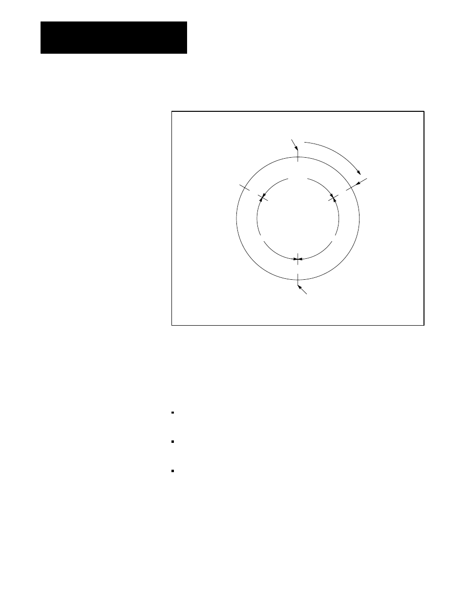
Figure C.2
Typical Timing Diagram for 0.01ĆSecond Timer
8Ć9 msec.
8Ć9 msec.
8Ć9
msec.
Start of program scan
Same 0.01Ćsec.
timer rung
Same 0.01Ćsec. timer rung
0.01Ćsec.
timer rung
Scan time = 25 msec (typical)
These multiple entries of the 0.01-second timer rung will help assure that
the accuracy of the timer accumulated value is within the accuracy limits
discussed above. Additional programming techniques can help to assure
that output devices controlled by the timer are energized or de-energized
after as precise a time delay as possible. You may want to include the
following:
Multiple entries of rungs which examine the timed bit of the timer to
condition an Output Energize instruction.
Immediate Input instructions to help assure that the timer is enabled as
quickly as possible after the external event occurs.
Immediate Output instructions to help assure that the output device is
energized/de-energized as quickly as possible after the Mini-Processor
sets the output image table bit to “1” or clears it to “0.”
Typical 10-msec timer rungs are shown in figure C.3. In Rung No. 1,
Immediate Input instructions precede Examine instructions addressed to
bits in input image table words 110 and 113. When used near the middle or
end of a program, the Immediate Input instructions help to assure that the
processor will be executing instructions based on accurate data.