Rockwell Automation 1772-LP3 PLC - 2/30 Programmable Controller Programming and Operations Manual User Manual
Page 185
Block Transfer
Chapter 10
10Ć2
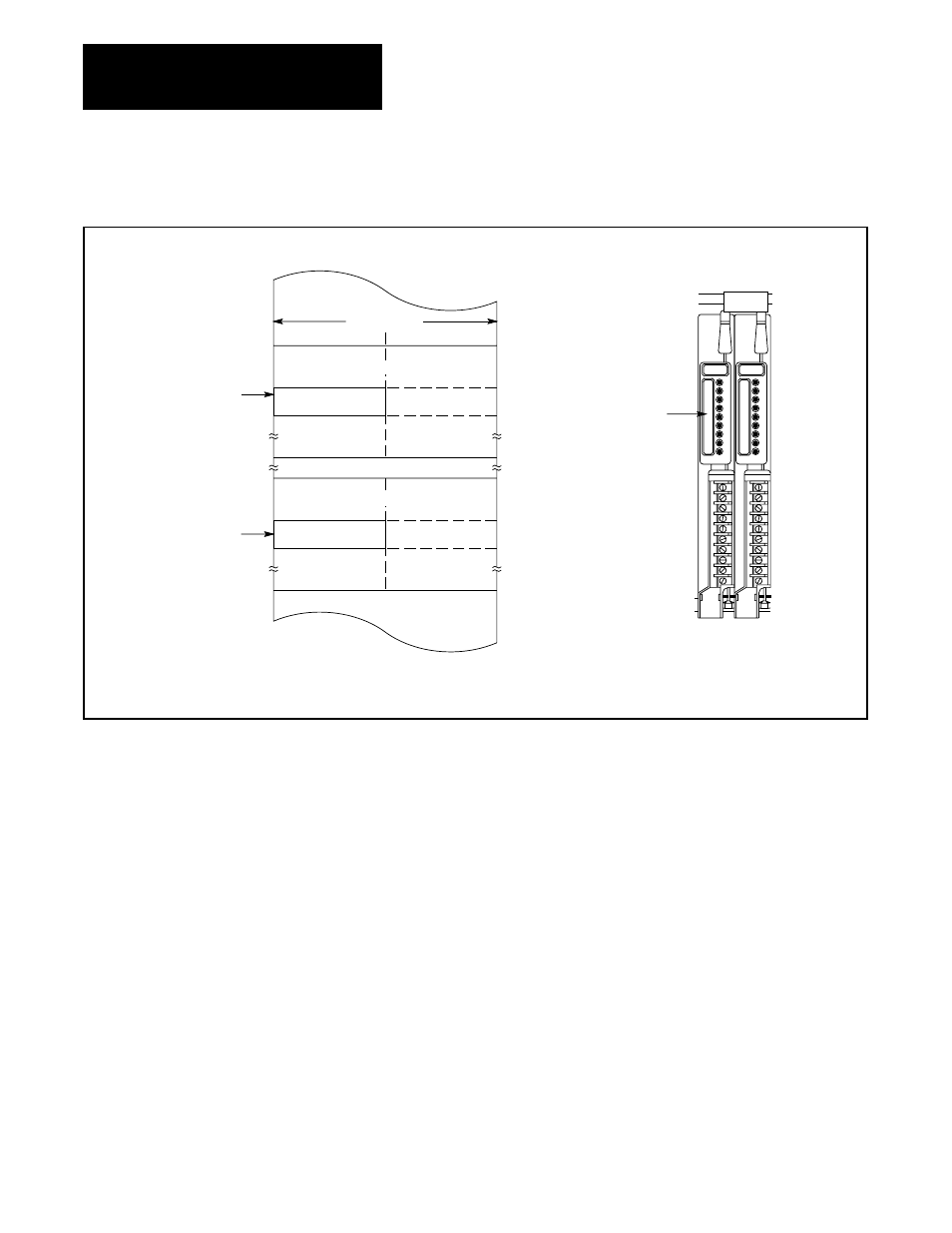
Figure 10.1
Module PositionĆImage Table Byte Relationship
ЙЙЙЙЙЙ
ЙЙЙЙЙЙ
Output Image Table
17 10 07 00 010
012
017
Output Image
Table Word,
Lower Byte
Control Byte
ЙЙЙЙЙЙ
ЙЙЙЙЙЙ
Input Image Table
110
112
117
Status Byte
Input Image
Table Word,
Lower Byte
Data Table
Bit Numbers
Block
Transfer
Module
Lower
Slot
Upper
Slot
The lower byte of the I/O image table words are used when the
module is in the lower slot and vice versa.
I/O Rack
The block transfer read or write operation (Figure 10.2) is initiated in the
program scan and completed in the I/O scan as follows:
1. Program scan – When the rung goes true, the instruction is enabled.
The number of words to be transferred and the read or write bit that
controls the direction of transfer are set by a bit pattern in the output
image table byte.
2. I/O scan – The processor requests a transfer by sending the output
image table byte data to the block transfer module during the scan of
the output image table. The module signals that it is ready to transfer.
The processor then interrupts the I/O scan and scans the timer/counter
accumulated area of the data table, looking for the address of the
module that is ready to transfer. The module address is stored in BCD
at a word address in the same manner as an accumulated value of a
timer is stored. The module address was entered by the programmer
when entering the block instruction parameters. The word address at
which the module address is stored is called the data address of the
instruction.