Using logic command/ status, Using reference/feedback, Using logic command/status – Rockwell Automation 20-COMM-E PowerFlex EtherNet/IP Adapter User Manual
Page 98: Table 5.f
5-6
Using the I/O
20-COMM-E EtherNet/IP Adapter User Manual
Publication 20COMM-UM010G-EN-P
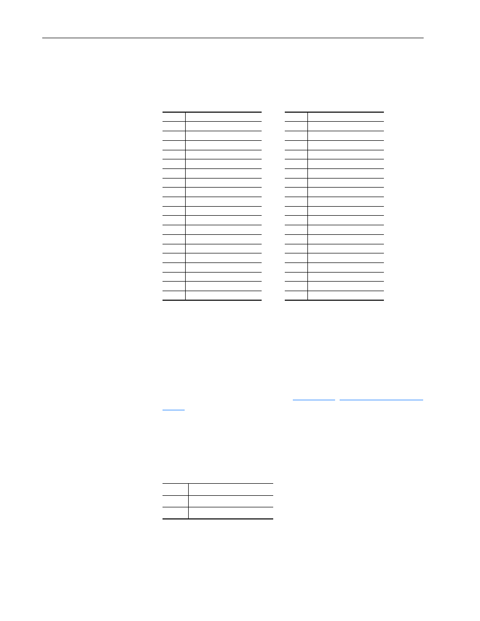
Table 5.F PLC-5, SLC 500, or MicroLogix 1100/1400 Controller I/O Image for Drives
with 32-bit Reference/Feedback and 32-bit Datalinks
These products include the following:
Using Logic Command/
Status
The Logic Command is a 16-bit word of control data produced by the
controller and consumed by the adapter. The Logic Status is a 16-bit word
of status data produced by the adapter and consumed by the controller.
PowerFlex 750-Series drives have a 32-bit Logic Command/Status—but
when using a 20-COMM-E adapter, only the first 16 bits can be used.
This manual contains the bit definitions for most compatible products
available at the time of publication in
,
. For other products, see their documentation.
Using Reference/Feedback
The Reference is produced by the controller and consumed by the adapter.
The Feedback is produced by the adapter and consumed by the controller.
The size of the Reference/Feedback is determined by the drive and
displayed with adapter Parameter 18 - [Ref/Fdbk Size].
When the Reference and Feedback are enabled and a ControlLogix
controller with a drive Add-on Profile or Classic Profile is used, specific
controller tags are automatically created, sized (16-bit or 32-bit), and placed
in the I/O image.
• PowerFlex 700S drives with Phase I or Phase II control
• PowerFlex 753 drives
• PowerFlex 700L drives with 700S control
• PowerFlex 755 drives
Word
Output I/O
Word
Input I/O
0
Logic Command
0
Logic Status
1
Reference (LSW)
1
Feedback (LSW)
2
Reference (MSW)
2
Feedback (MSW)
3
Datalink In A1 (LSW)
3
Datalink Out A1 (LSW)
4
Datalink In A1 (MSW)
4
Datalink Out A1 (MSW)
5
Datalink In A2 (LSW)
5
Datalink Out A2 (LSW)
6
Datalink In A2 (MSW)
6
Datalink Out A2 (MSW)
7
Datalink In B1 (LSW)
7
Datalink Out B1 (LSW)
8
Datalink In B1 (MSW)
8
Datalink Out B1 (MSW)
9
Datalink In B2 (LSW)
9
Datalink Out B2 (LSW)
10
Datalink In B2 (MSW)
10
Datalink Out B2 (MSW)
11
Datalink In C1 (LSW)
11
Datalink Out C1 (LSW)
12
Datalink In C1 (MSW)
12
Datalink Out C1 (MSW)
13
Datalink In C2 (LSW)
13
Datalink Out C2 (LSW)
14
Datalink In C2 (MSW)
14
Datalink Out C2 (MSW)
15
Datalink In D1 (LSW)
15
Datalink Out D1 (LSW)
16
Datalink In D1 (MSW)
16
Datalink Out D1 (MSW)
17
Datalink In D2 (LSW)
17
Datalink Out D2 (LSW)
18
Datalink In D2 (MSW)
18
Datalink Out D2 (MSW)
Size
Valid Values
16-bit
-32768 to 32767
32-bit
-2147483648 to 2147483647