Figure 6.27, Table sho – Rockwell Automation 20-COMM-E PowerFlex EtherNet/IP Adapter User Manual
Page 150
6-24
Using Explicit Messaging
20-COMM-E EtherNet/IP Adapter User Manual
Publication 20COMM-UM010G-EN-P
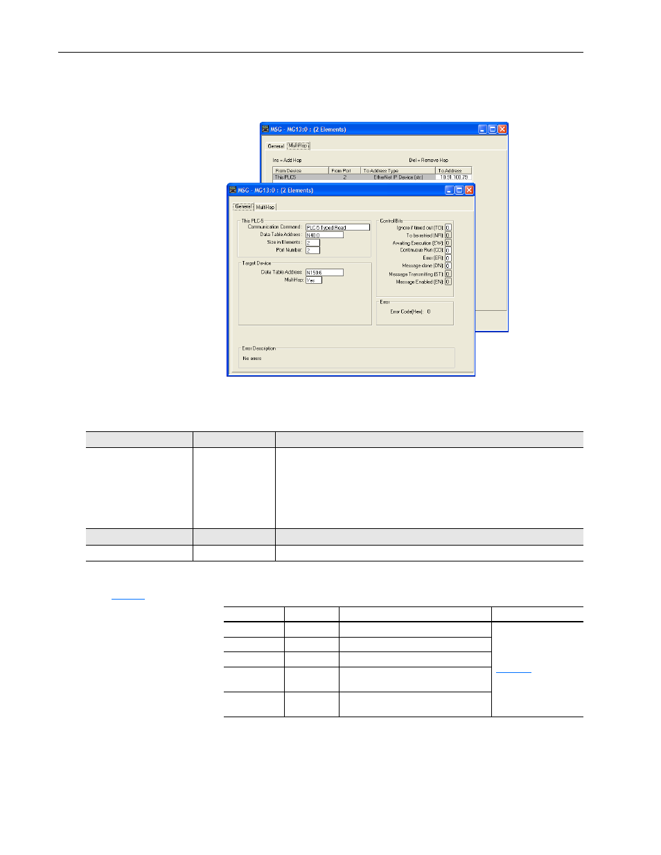
PLC-5 Controller – Formatting a Message to Read a Single Parameter
Figure 6.27 Read Single Message Configuration Screens
The following table identifies the data that is required in each box to
configure a message to read a parameter.
General Tab
Example Value
Description
Communication Command
Data Table Address
Size in Elements
Port Number
Data Table Address
MultiHop
PLC-5 Typed Read
N40:0
2
(1)
2
N150:6
(2)
Yes
Controller type and command type for controller to read data from the drive.
An unused controller data table address containing the message instruction. This
address is the starting word of the destination file.
Number of elements (words) to be transferred. Each element size is a 16-bit integer.
Controller port to which the network is connected.
Specific starting address of the source file in the drive.
Enables communication to allow network messaging to be routed to the drive.
MultiHop Tab
Example Value
Description
To Address
10.91.100.79
IP address of the adapter connected to the drive.
(1)
Because the N-files used for the data transfer occupies two contiguous 16-bit words, the Size in Elements must always be set to 2 regardless of whether the
parameter being read is a 16-bit integer or a 32-bit integer.
(2)
See
for N-file addressing. Below are some examples of how to address N-files:
N-File Address
Data Type
Description
Notes
N150:6
32-bit integer
Parameter 3 of PowerFlex 70 drive
Example ladder logic
rungs are shown in
different parameter data
types.
N155:14
32-bit REAL
Parameter 7 of PowerFlex 750-Series drive
N155:200
32-bit integer
Parameter 725 of PowerFlex 750-Series drive
N209:154
32-bit REAL
Port 5: Parameter 77 of 24V I/O module in
PowerFlex 750-Series drive
N211:50
16-bit integer
Port 6: Parameter 25 of 20-COMM-E adapter
in PowerFlex 750-Series drive