Understanding controller data table addresses – Rockwell Automation 20-COMM-E PowerFlex EtherNet/IP Adapter User Manual
Page 114
5-22
Using the I/O
20-COMM-E EtherNet/IP Adapter User Manual
Publication 20COMM-UM010G-EN-P
Understanding Controller Data Table Addresses
Because PLC-5, SLC 500, and MicroLogix 1100/1400 controllers are 16-bit
platforms and are used with the 32-bit 20-COMM-E adapter, the data will
be transposed from the least-significant word (LSW) to the most-significant
word (MSW) in the controller.
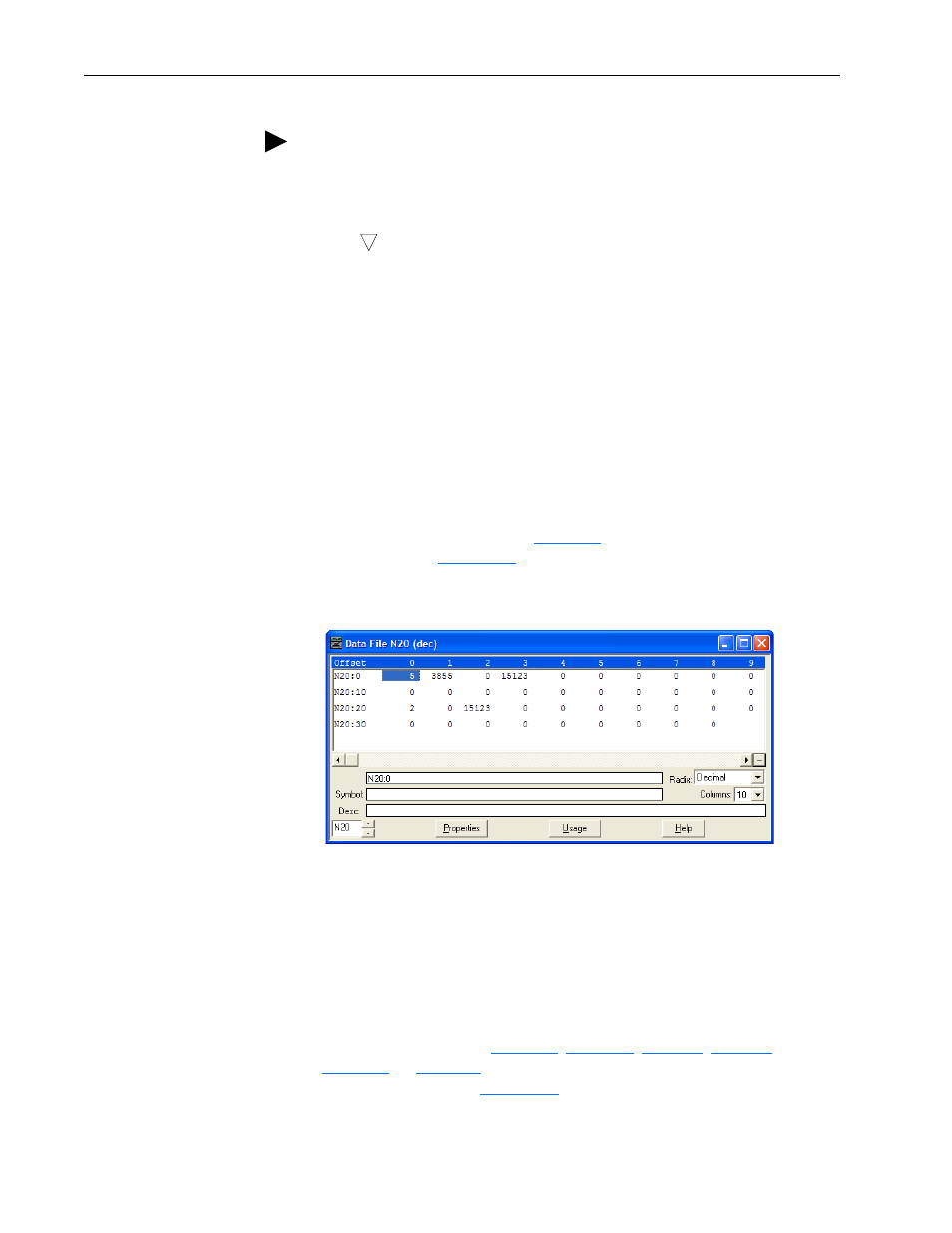
When the I/O was configured (
), an available data table address
(N20) was used.
shows the entire data file address structure for
this example.
Figure 5.12 Data File Table for Example Ladder Logic Program
Important: The N20:0 data table address in this example is used to set a
control timeout value (in seconds) which determines how long
it will take the adapter to detect a communication loss. Enter a
valid value (1…32767) for N20:0. A value of zero (0) is not
valid, because it disables the timeout and all I/O connections
(Logic Command/Status, Reference/Feedback, and Datalinks)
intended for the drive will not execute. A timeout value of
5…20 seconds is recommended.
Depending on the drive,
, or
show the I/O definitions as they relate to the N20
data table addresses in
TIP: When using a drive that has 16-bit Datalinks (PowerFlex 70,
PowerFlex 700, and PowerFlex 700H drives) to transfer a 32-bit parameter,
two contiguous drive Datalink parameters (for example, Data Out A1/A2,
B1/B2, and so forth) are required. To determine if a parameter is a 32-bit
parameter, see the Parameter section in the drive documentation and look
for a
symbol in the ‘No.’ column. (All parameters in PowerFlex 700
Series B drives are 32-bit parameters.) For example, parameter 3 - [Output
Current] in a PowerFlex 70 EC drive is a 32-bit parameter. When using a
drive that has 32-bit Datalinks (PowerFlex 700 VC, PowerFlex 700S, and
PowerFlex 750-Series drives), only one drive Datalink parameter is required
to transfer any parameter.
32