Note that – Rockwell Automation 20-COMM-E PowerFlex EtherNet/IP Adapter User Manual
Page 190
6-64
Using Explicit Messaging
20-COMM-E EtherNet/IP Adapter User Manual
Publication 20COMM-UM010G-EN-P
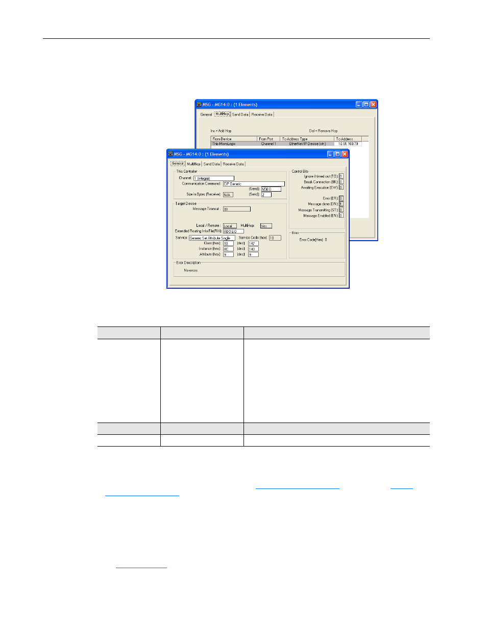
MicroLogix 1100/1400 Controller – Formatting a Message to Write a Single
Parameter Using Generic Get/Set Attribute Service
Figure 6.79 Generic Set Attribute Single Message Configuration Screens
The following table identifies the data that is required in each box to
configure a message to write a single parameter.
General Tab
Example Value
Description
Channel
Comm… Command
Data Table Address
Size in Bytes
Extended Routing…
Service
(1)
Class
Instance
(2)
Attribute
(3)
1
CIP Generic
N50:0
2
(4)
RIX16:0
Generic Set Attribute Single
93 or 9F (Hex.)
(5)
140 (Dec.)
9 or 10 (Dec.)
Controller port to which the network is connected.
Used to access the Parameter Object in the adapter.
An unused controller data table address containing the message
instruction. This address is the starting word of the destination file.
Number of bytes to be transferred. Each byte size is an 8-bit integer.
An unused routing information file for the controller.
Code for the requested service.
Class ID for the DPI Parameter Object.
Instance number is the same as the parameter number.
Attribute number for the Parameter Value attribute.
MultiHop Tab
Example Value
Description
To Address
10.91.100.79
IP address of the adapter connected to the drive.
(1)
The default setting for Service is ‘Custom’, enabling entry of a Service Code not available from the Service pull-down menu. When choosing a
Service other than ‘Custom’ from the pull-down menu, an appropriate Hex. value is automatically assigned to the Service Code box which is
dimmed (unavailable).
(2)
The instance is the parameter number in the drive (Port 0). For example, to write to parameter 4 of a peripheral in Port 5 of a PowerFlex
750-Series drive, the instance would be 21504 + 4 = 21508. See
DPI Parameter Object on page C-16
(Class code 0x9F) to determine the instance number.
(3)
Setting the Attribute value to ‘9’ will write the parameter value to the drive’s Nonvolatile Storage (EEPROM) memory, which retains the
parameter value even after the drive is power cycled.
Important: When set to ‘9’, the EEPROM may quickly exceed its life cycle and cause
the drive to malfunction. Setting the Attribute value to ‘10’ will write the parameter value to temporary memory, which deletes the parameter
value after the drive is power cycled. When frequent write messages are required, we recommend using the ‘10’ setting.
(4)
In this example, Accel Time 1 is a 16-bit integer parameter requiring the Size in Bytes field to be set to ‘2’. If the parameter being written to is
a 32-bit integer, the Size in Bytes must be set to ‘4’. When using a PowerFlex 700S or PowerFlex 750-Series drive, Accel Time 1 is a floating
point number requiring the Size in Bytes to be set to ‘4’. See the drive documentation to determine the size of the parameter and its data type
(16-bit or 32-bit integer or REAL).
(5)
for limitations of PowerFlex 7-Class and PowerFlex 750-Series drives when using DPI Parameter Object Class
code 0x93 or Host DPI Parameter Object Class code 0x9F for explicit messaging.