Figure 6.89, To store the response v – Rockwell Automation 20-COMM-E PowerFlex EtherNet/IP Adapter User Manual
Page 196
6-70
Using Explicit Messaging
20-COMM-E EtherNet/IP Adapter User Manual
Publication 20COMM-UM010G-EN-P
In this example, the parameters have the following values.
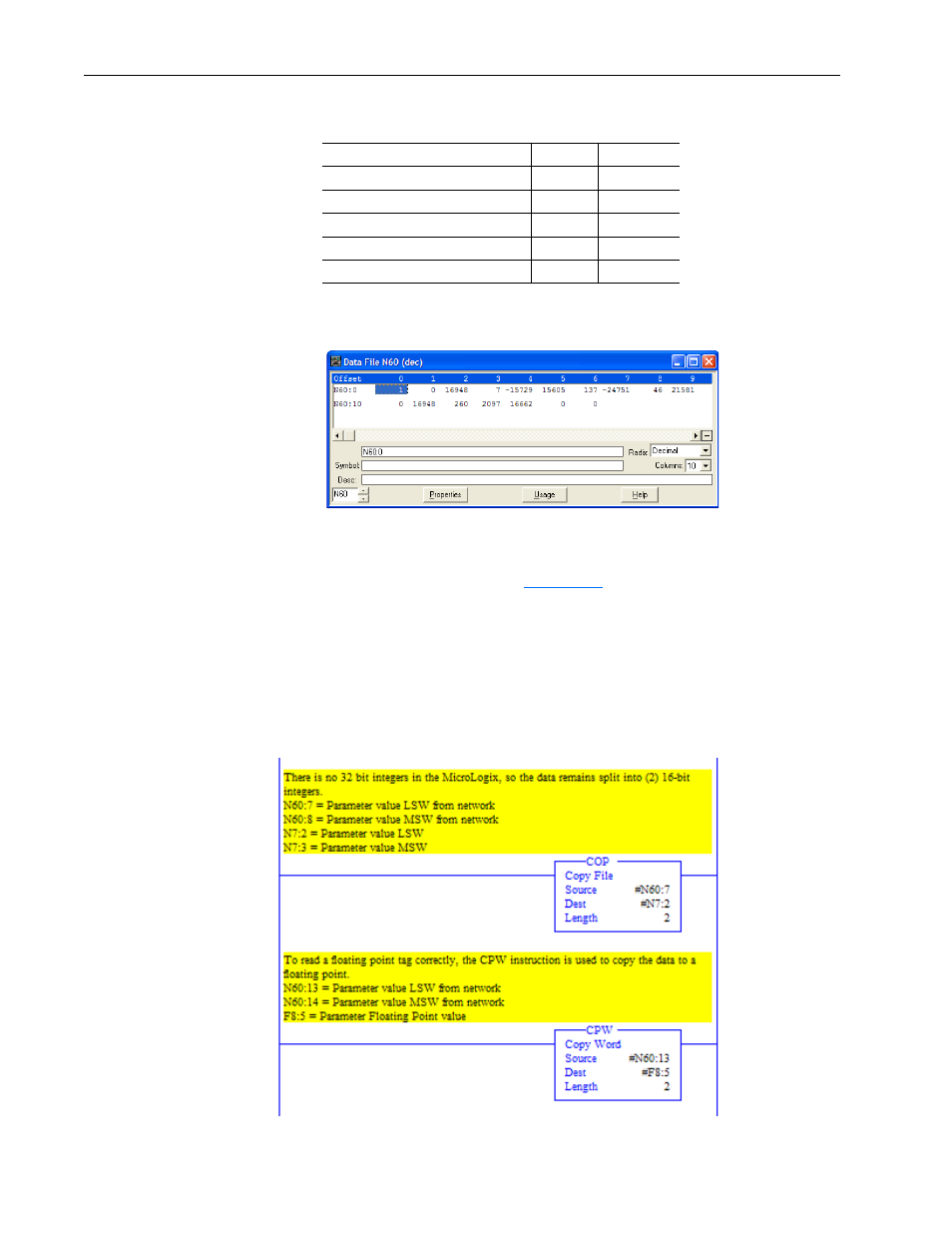
Figure 6.89 Example Scattered Read Response Data File for PowerFlex 750-Series
Drive
The PowerFlex 750-Series drive uses 32-bit integer and REAL parameters.
A COP or CPW command must be used to copy the N60 integer array to a
16-bit integer or floating tag.
shows the ladder logic used for
this example. If the parameter data type is a 32-bit integer, the data remains
split into two 16-bit integers because there are no 32-bit integers in the
MicroLogix 1100/1400 controller. If the parameter data type is a REAL,
then the destination tag is a floating point. See the drive documentation to
determine the parameter data type (32-bit integer or REAL).
Figure 6.90 Example Ladder Logic to Copy Response Data for PowerFlex 750-Series
Drive
PowerFlex 7-Class Drive Parameter
Address
Read Value
1 - [Output Freq]
N60:1
32.5 Hz
3 - [Output Current]
N60:4
0.01 Amp
6 - [Output Voltage]
N60:7
118.7V AC
12 - [DC Bus Voltage]
N60:10
329.2V DC
17 - [Analog In2 Value]
N60:13
8.318 mA
Parameter 137 -
[Open Loop Fdbk]
PowerFlex
750-Series Drives
Parameter 001 -
[Output Freq]