Rockwell Automation 20-COMM-E PowerFlex EtherNet/IP Adapter User Manual
Page 79
Configuring the I/O
4-33
20-COMM-E EtherNet/IP Adapter User Manual
Publication 20COMM-UM010G-EN-P
Create SLC 500 Ladder Logic for the Control Timeout
1. In the RSLogix 500 project window treeview under Program Files
double-click on LAD 2.
2. Insert a ladder rung.
3. Double-click the rung to display the rung editor.
4. Enter MSG WRITE 500CPU LOCAL Nxx:n, where:
xx is an unused data file number (for example, N10:n), and
n is an unused element of the data file chosen for xx (for example, N10:0)
5. Press Enter.
6. Insert another separate rung.
7. Double-click the rung to display the rung editor.
8. Enter BST XIC Nxx:n/DN NXB XIC Nxx:n/ER BND OTU Nxx:n/
EN, where:
xx and n must correspond to the assigned data file number and element
(for example, N10:0) for the message created in steps 2…5.
Important: The information must be entered with appropriate numbers
for ‘xx’ and ‘n’ for your application, and with spaces and
forward slashes exactly as shown.
9. Press Enter.
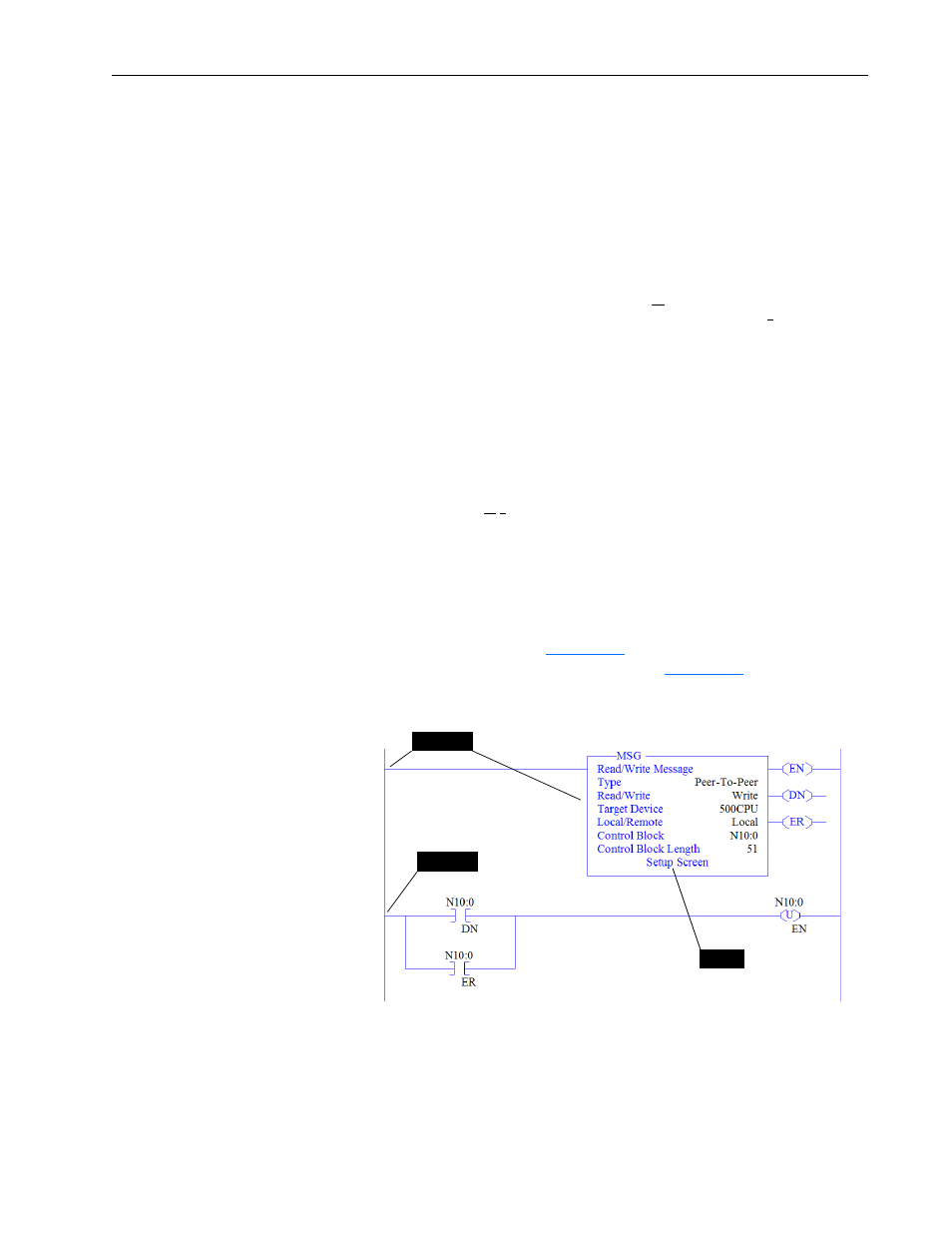
10. In the MSG instruction (
), double-click Setup Screen to
launch the message configuration screen (
).
Figure 4.13 SLC 500 Ladder Logic for the Control Timeout
11. Configure the General tab fields by entering or verifying the
information shown in the message configuration screen.
Steps 6…9
Step 10
Steps 2…5