E (see, Figure 2.3 – Rockwell Automation 20-COMM-E PowerFlex EtherNet/IP Adapter User Manual
Page 25
Installing the Adapter
2-5
20-COMM-E EtherNet/IP Adapter User Manual
Publication 20COMM-UM010G-EN-P
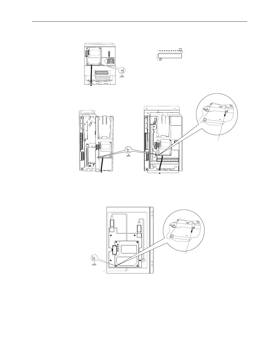
Figure 2.3 Mounting and Grounding the Adapter
NOTE: When installing the adapter in a PowerFlex 750-Series drive, see
the 20-750-20COMM and 20-750-20COMM-F1 Communication Carrier
Cards Installation Instructions, publication 750COM-IN001, supplied with
the card.
X1
X2
Drive
Adapter
Internal Interface Cable
folded behind the adapter
and in front of the drive.
PowerFlex 70 - All Frame Sizes
(Adapter mounts in drive.)
Verify metal ground tab is bent 90° and
is under the adapter before tightening
screw. After tightening the screw, verify
continuity exists between the head of
the screw and drive ground.
Ground Tab Detail
PowerFlex 700 Frames 0 and 1
PowerFlex 700S Frames 0 and 1
(Adapter mounts on door.)
PowerFlex 700 Frames 2 and Larger
PowerFlex 700S Frames 2 through 6
(Adapter mounts in drive.)
0.9 N•m
(8.0 lb•in)
4 Places
Verify metal ground tab is bent 90° and
is under the adapter before tightening
screw. After tightening the screw, verify
continuity exists between the head of
the screw and drive ground.
PowerFlex 700H Frames 9 and Larger
PowerFlex 700S Frames 9 and Larger
(Adapter mounts behind HIM panel.)
Ground Tab Detail
0.9 N•m
(8.0 lb•in)
4 Places
0.9 N•m
(8.0 lb•in)
4 Places