Rockwell Automation 20-COMM-E PowerFlex EtherNet/IP Adapter User Manual
Page 65
Configuring the I/O
4-19
20-COMM-E EtherNet/IP Adapter User Manual
Publication 20COMM-UM010G-EN-P
When using Datalinks, up to 8 drive [Data In xx] parameters (300…307)
and/or up to 8 [Data Out xx] parameters (310…317) must be assigned to
point to the appropriate drive parameters for your application.
7. After setting the information in the drive’s New Module screen, click
OK.
The Module Properties screen appears.
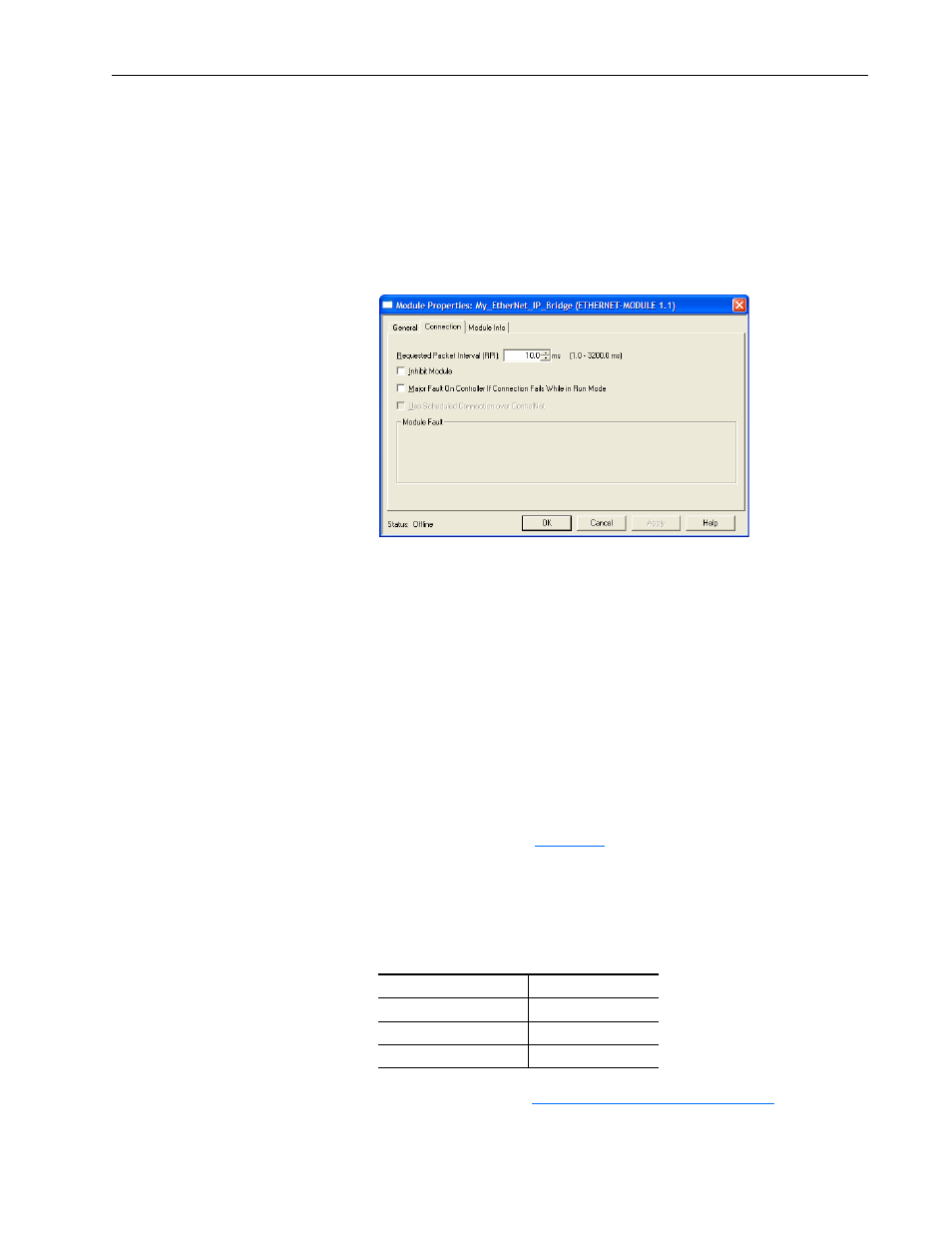
8. Click the Connection tab.
9. In the ‘Requested Packet Interval (RPI)’ box, set the value to 5.0
milliseconds or greater.
This value determines the maximum interval that a controller should
use to move data to and from the adapter. To conserve bandwidth, use
higher values for communicating with low priority devices. For this
example, leave the ‘Inhibit Module’ and ‘Major Fault …’ boxes
unchecked.
10. Click OK.
The new node (‘My_PowerFlex_70_EC_Drive’ in this example) now
appears under the bridge (‘My_EtherNet_IP_Bridge’ in this example)
in the I/O Configuration folder. If you double-click the Controller Tags,
you will see that module-defined data types and tags have been
automatically created (
). After you save and download the
configuration, these tags allow you to access the Input and Output data
of the drive via the controller’s ladder logic.
For this example, all Datalinks (A, B, C, and D) are enabled. The Input
Size is set to 12 words and the Output Size is set to 10 words. Also, the
following adapter I/O parameters are set to the following values.
11. Reset the adapter (see
Resetting the Adapter on page 3-16
) or power
cycle the drive.
Adapter Parameter No.
Setting
23 - [DPI I/O Cfg]
xxxx xxxx xxx1 1111
35 - [M-S Input]
xxxx xxxx xxx1 1111
36 - [M-S Output]
xxxx xxxx xxx1 1111