Figure 4.14 – Rockwell Automation 20-COMM-E PowerFlex EtherNet/IP Adapter User Manual
Page 80
4-34
Configuring the I/O
20-COMM-E EtherNet/IP Adapter User Manual
Publication 20COMM-UM010G-EN-P
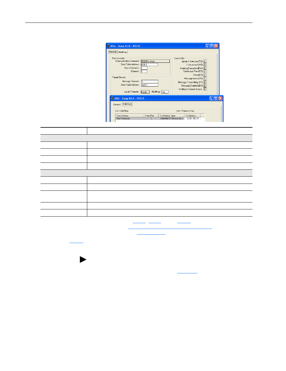
Figure 4.14 SLC 500 Message Configuration Screens for the Control Timeout
General Tab Box
Setting
This Controller
Communication Command
This setting is unavailable (grayed out) and is established when the message is created in the ladder rung.
Data Table Address
(1)
N20:0. An unused controller data table address containing the control timeout value to be written.
Size in Elements
(2)
1. Number of elements (words) to be transferred. Each element size is a 16-bit integer.
Channel
1. Controller port to which the network is connected.
Target Device (data for adapter/drive)
Message Timeout
5. Message timeout duration in seconds.
Data Table Address
(3)
N42:3. Specific starting address of the destination file in the drive.
MultiHop
Yes. Enables communication to allow network messaging to be routed to the adapter/drive. When ‘Yes’ is
selected, a MultiHop tab appears on the message configuration screen.
MultiHop Tab Box
Setting
To Address
10.91.100.79. The IP address of the adapter connected to the drive.
(1)
For details on data table addresses for this example project, see
starting on
(2)
For details to determine element size for a specific drive, see
Understanding Controller Data Table Addresses on page 5-22
(3)
For details on setting the control timeout value and its function, see
. The Control Timeout (N42:3) is stored in RAM. If the
20-COMM-E adapter is power cycled, the Control Timeout Message must be re-sent. If the Control Timeout is not changed from a non-zero value, the
control message (
) will error out.
TIP: The Control Timeout (N42:3) must be changed to a non-zero value
(5…20 seconds recommended). If the Control Timeout is not changed from
a non-zero value, the control message (
) will error out. The
Control Timeout is stored in RAM. If the adapter is power cycled, the
Control Timeout Message must be re-sent.