Rockwell Automation 20-COMM-E PowerFlex EtherNet/IP Adapter User Manual
Page 40
3-12
Configuring the Adapter
20-COMM-E EtherNet/IP Adapter User Manual
Publication 20COMM-UM010G-EN-P
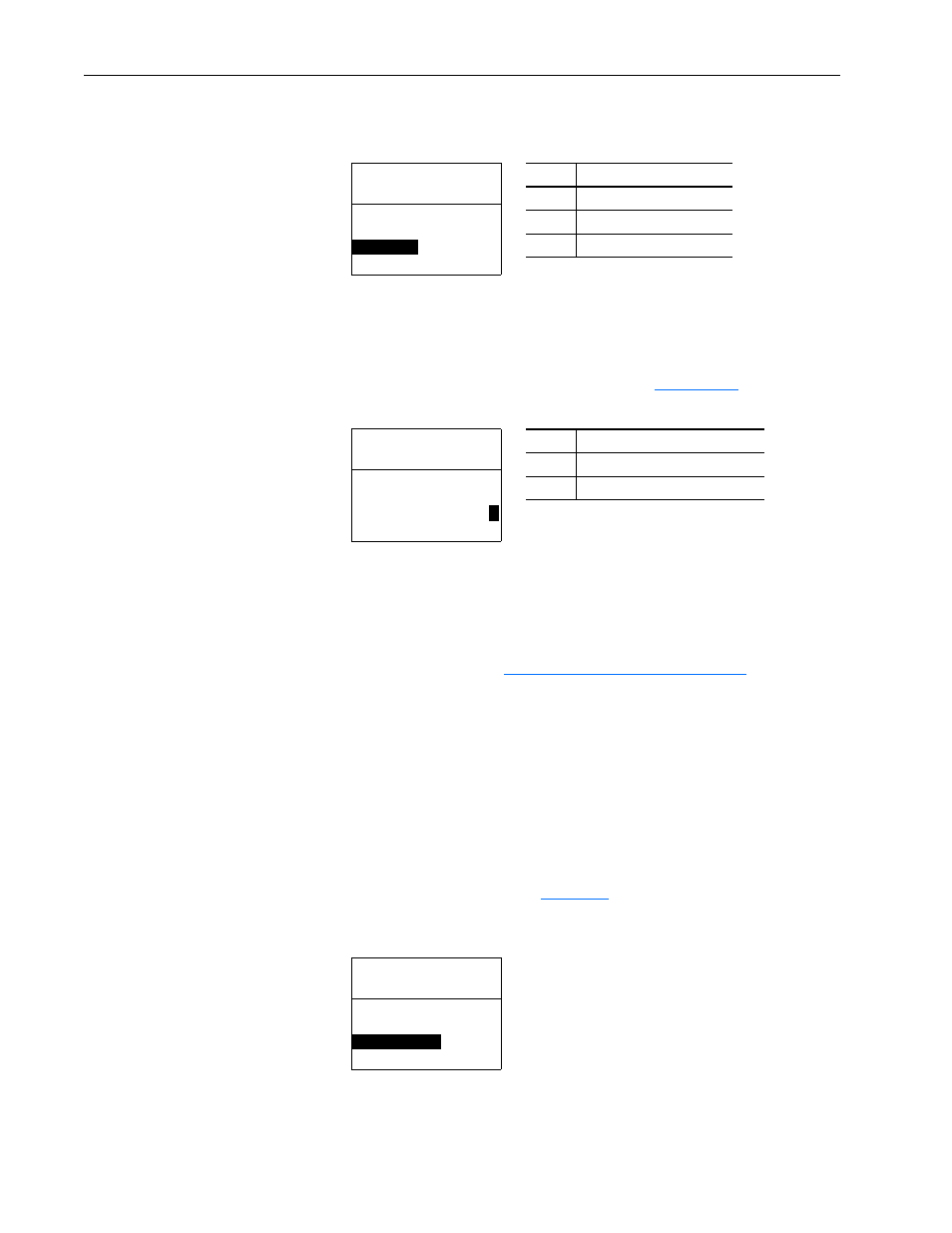
4. If desired, set Parameter 39 - [Peer B Input] to select the destination
of the data to input to the drive as Peer B.
5. If the adapter receives a Logic Command, set the bits in Parameter 40 -
[Peer Cmd Mask] that the drive should use.
The bit definitions for the Logic Command word will depend on the
drive to which the adapter is connected. See
or the drive
documentation.
If the adapter receives a Logic Command from both a master device and
a peer device, each command bit must have only one source. The source
of command bits set to ‘0’ will be the master device. The source of
command bits set to ‘1’ will be the peer device.
6. Reset the adapter (see
Resetting the Adapter on page 3-16
) so that
changes to Parameter 40 - [Peer Cmd Mask] take effect.
7. Set Parameter 46 - [Peer Inp Timeout] to the maximum amount of
time the adapter will wait for a message before timing out.
Important: This value must be greater than the product of Parameter
52 - [Peer Out Time] multiplied by Parameter 53 - [Peer
Out Skip] in the adapter from which you are receiving I/O.
For example, if the value of Parameter 52 - [Peer Out Time] is 2.00
seconds and the value of Parameter 53 - [Peer Out Skip] is 2 (see
example screen in step 4 on
), then Parameter 46 - [Peer Inp
Timeout] needs to have a value greater than 4.00, such as 5.00 in the
example screen below.
Port 5 Device
20-COMM-E
Parameter #: 39
Peer B Input
2
DL A Input
Value
Description
0
Off (Default)
1
Logic Command/Reference
2…5
Datalink A, B, C, or D Input
Value
Description
0
Ignore this command bit. (Default)
1
Use this command bit.
Port 5 Device
20-COMM-E
Parameter #: 40
Peer Cmd Mask
0 0 0 0 0 0 0 0 0 0 0 0 0 0 0
0
Bit 0
B00
Port 5 Device
20-COMM-E
Parameter #: 46
Peer Inp Timeout
5.00
s
0.01 <> 10.00
Default = 10.00 s