Rockwell Automation 20-COMM-E PowerFlex EtherNet/IP Adapter User Manual
Page 63
Configuring the I/O
4-17
20-COMM-E EtherNet/IP Adapter User Manual
Publication 20COMM-UM010G-EN-P
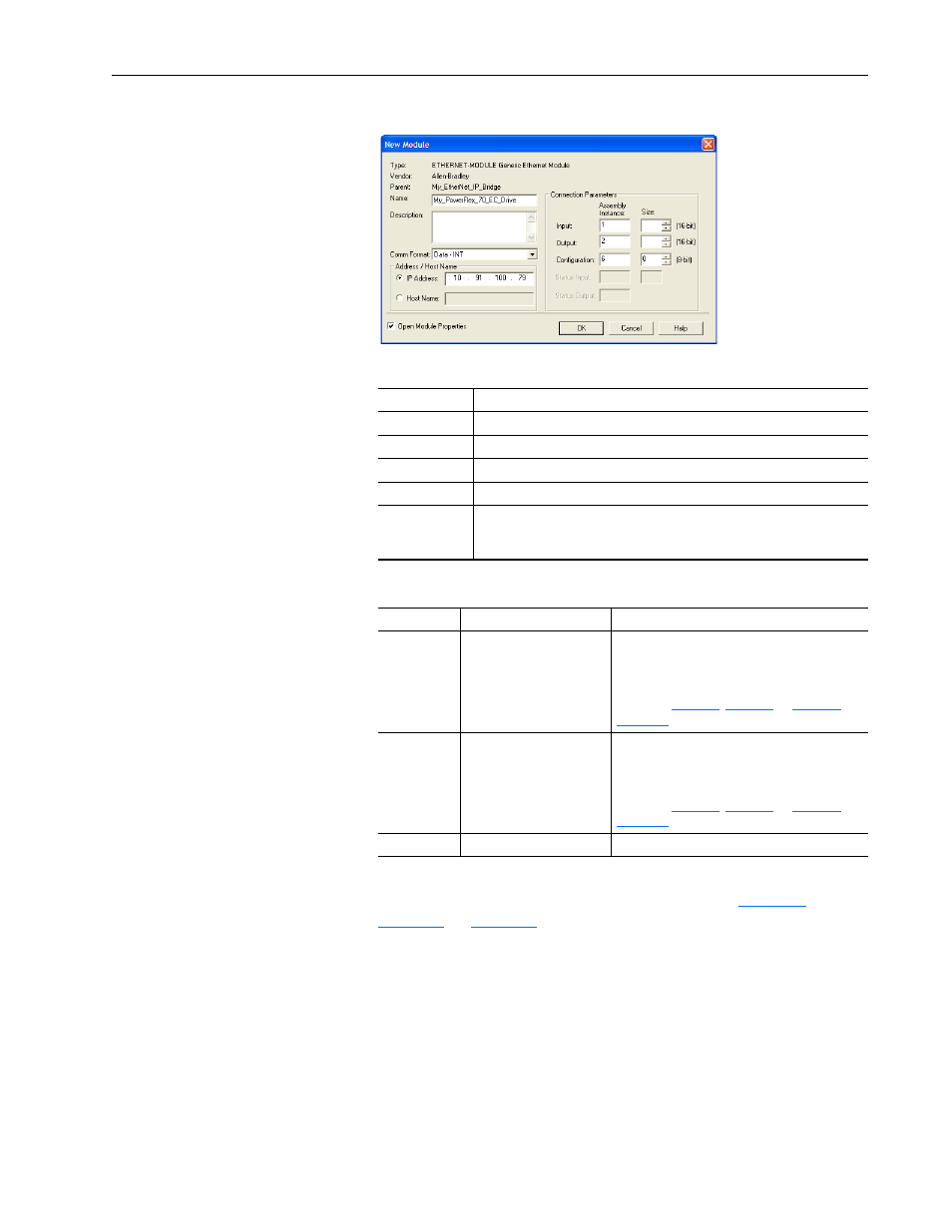
The drive’s New Module screen appears.
5. Edit the following information about the drive and adapter.
6. Under Connection Parameters, edit the following information.
Depending on the size of the drive’s Reference/Feedback and the
number of Datalinks used in your I/O configuration,
Table 4.B
defines the number of 16-bit words that you
need to enter for the Input Size and Output Size boxes.
Box
Setting
Name
A name to identify the drive and adapter.
Description
Optional – description of the drive/adapter.
Comm Format
Data - INT (This setting formats the data in 16-bit words.)
IP Address
The IP address of the adapter.
Open Module
Properties
When this box is checked, clicking
OK opens additional module properties
screens to further configure the drive/adapter. When unchecked, clicking
OK closes the drive’s New Module screen. For this example, check this box.
Box
Assembly Instance
Size
Input
1 (This value is required.)
The value will vary based on your application
(setting of
Parameters 23 - [DPI I/O Cfg] and 36
- [M-S Output]) and the size (16-bit or 32-bit) of
the Reference/Feedback and Datalinks in the
drive. See
Table 4.B
.
Output
2 (This value is required.)
The value will vary based on your application
(setting of
Parameters 23 - [DPI I/O Cfg] and 35
- [M-S Input]) and the size (16-bit or 32-bit) of
the Reference/Feedback and Datalinks in the
drive. See
Table 4.B
.
Configuration
6 (This value is required.)
0 (This value is required.)