Rockwell Automation 20-COMM-E PowerFlex EtherNet/IP Adapter User Manual
Page 38
3-10
Configuring the Adapter
20-COMM-E EtherNet/IP Adapter User Manual
Publication 20COMM-UM010G-EN-P
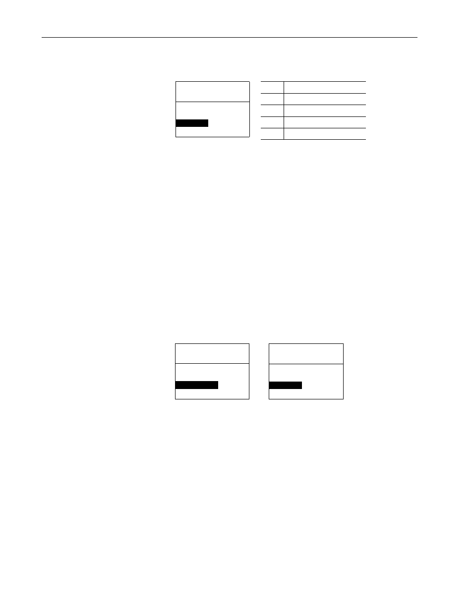
3. If desired, set Parameter 50 - [Peer B Output] to select an additional
source of the data to output to the network.
4. Set Parameters 52 - [Peer Out Time] and 53 - [Peer Out Skip] to
establish the minimum and maximum intervals between peer messages.
Because the adapter transmits peer messages when a change-of-state
condition occurs, minimum and maximum intervals are required.
– The minimum interval ensures that the adapter does not transmit
messages on the network too often, thus minimizing network traffic.
Set the minimum interval with Parameter 52 - [Peer Out Time].
– The maximum interval ensures that the adapter transmits messages
often enough so that the receiving adapter(s) can receive recent data
and verify that communications are working or, if communications
are not working, can timeout. The maximum interval is the value of
Parameter 52 - [Peer Out Time] multiplied by the value of
Parameter 53 - [Peer Out Skip].
In the example below, the minimum interval is set to 2.00 seconds
(Parameter 52 - [Peer Out Time]), and the maximum interval is set to
4.00 seconds (2.00 x ‘2’ setting of Parameter 53 - [Peer Out Skip]).
5. Set Parameter 51 - [Peer Out Enable] to ‘1’ (On).
The adapter will transmit the data selected in Parameters 49 - [Peer A
Output] and 50 - [Peer B Output] to the network. Another adapter
must be configured to receive the peer I/O data.
Port 5 Device
20-COMM-E
Parameter #: 50
Peer B Output
2
DL A Input
Value
Description
0
Off (Default)
1
Logic Command/Reference
2…5
Datalink A, B, C, or D Input
6…9
Datalink A, B, C, or D Output
Port 5 Device
20-COMM-E
Parameter #: 52
Peer Out Time
2.00
s
0 <> 10.00
Port 5 Device
20-COMM-E
Parameter #: 53
Peer Out Skip
2
1 <>16
Default = 10.00 s
Default = 1