Table 5.m, Table 5.n – Rockwell Automation 20-COMM-E PowerFlex EtherNet/IP Adapter User Manual
Page 121
Using the I/O
5-29
20-COMM-E EtherNet/IP Adapter User Manual
Publication 20COMM-UM010G-EN-P
Table 5.M Controller and Program Data Table Address Descriptions for Example
Logic Status/Feedback Ladder Logic Program
Table 5.N Program and Controller Data Table Address Descriptions for Example
Logic Command/Reference Ladder Logic Program
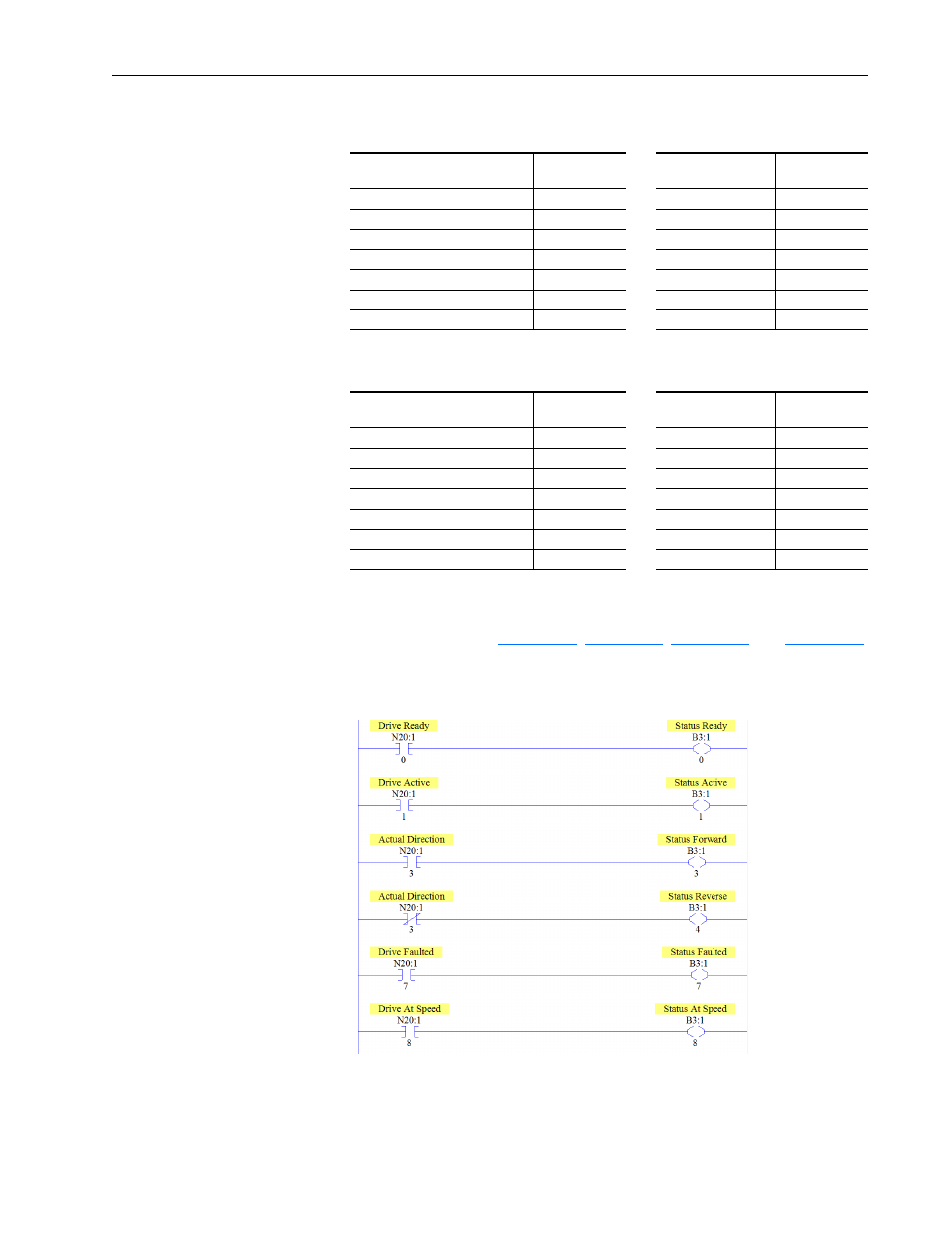
An example ladder logic program that uses these descriptive controller data
table addresses and passes their data to the descriptive program data table
addresses is shown in
Figure 5.13 PLC-5, SLC 500, or MicroLogix 1100/1400 Example Ladder Logic
Program for Logic Status
Description
Controller Data
Table Address
Description
Program Data
Table Address
Drive Ready
N20:1/0
Status Ready
B3:1/0
Drive Active
N20:1/1
Status Active
B3:1/1
Actual Direction (XIO)
N20:1/3
Status Forward
B3:1/3
Actual Direction (XIC)
N20:1/3
Status Reverse
B3:1/4
Drive Faulted
N20:1/7
Status Faulted
B3:1/7
Drive At Speed
N20:1/8
Status At Speed
B3:1/8
Speed Feedback
N20:3
Speed Feedback
B30:3
Description
Program Data
Table Address
Description
Controller Data
Table Address
Command Stop
B3:20/0
Drive Stop
N20:20/0
Command Start
B3:20/1
Drive Start
N20:20/1
Command Jog
B3:20/2
Drive Jog
N20:20/2
Command Clear Faults
B3:20/3
Drive Clear Faults
N20:20/3
Command Forward Reverse (XIO) B3:20/4
Drive Forward
N20:20/4
Command Forward Reverse (XIC) B3:20/4
Drive Reverse
N20:20/5
Speed Reference
N30:22
Speed Reference
N20:22
PowerFlex 70
and PowerFlex
750-Series
Drives