Festo DGC-HD User Manual
Page 21
DGC-HD
Festo – DGC-HD – 1304NH English
21
•
Observe the required support spacings. The diagrams (
12 Characteristic curves) show the sup-
port spacing, which is dependent on the mounting position and effective load. If the specified min-
imum distances are exceeded, it is imperative to carry out an individual functional test.
Note
Unsuitable mounting techniques can damage the DGC-HD.
•
Make sure that the mounting components are outside the positioning range of the
slide.
•
Fasten the DGC-HD.
•
Please select the corresponding accessories from our catalogue (
www.festo.com/catalogue).
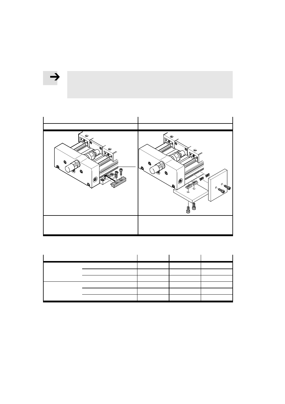
Profile mounting
Slot nut mounting
MUE
NST
aA
Profile mounting in the slot
aA of the mounting
surface
8
Slot nut mounting in slot
aA.
When tilted, the slot nuts slide into the slot at
each position of the profile
Tab. 1
•
Tighten the mounting screws uniformly with the following tightening torque.
Size
18
25
40
Screw
MUE
M5
M5
M8
NST (lateral)
M5
M5
M6
NST (underneath)
M5
M6
M6
Tightening torque
MUE
[Nm]
5
5
20
NST (lateral)
[Nm]
5.9
5.9
9.9
NST (underneath)
[Nm]
5.9
9.9
9.9
Tab. 2