SkyTrak 6036 Service Manual User Manual
Page 45
Section 4
Operator's Cab
Model 6036/6036T S/N 9B0500 thru 14833
4-9
+
+
3
1
2
4
3
1
2
MAX.
OUTPUT
MAX.
OUTPUT
DEAD
BAND
DEAD
BAND
45
2
2
45
45
2
COM
NO
NC
COM
NO
NC
COM
NO
NC
COM
NO
NC
B A
- +
B A
- +
B A
- +
B A
- +
RAISE/LOWER
EXTEND/RETRACT
RAISE/LOWER
CIRCUIT
BREAKERS
CONTROL VALVE
EXTEND/RETRACT
RAISE/LOWER
R L C T
R L C T
C B A
FRONT SWITCH
REAR SWITCH
LH SWITCH
RH SWITCH
EXTEND/RETRACT
JUMPER
7 GRD WIRES
RAISE
RETRACT EXTEND
LOWER
Gray
Yellow
Orange
Red
Black
Black
Blue
Gray
Yellow
Orange
Red
Black
Black
Blue
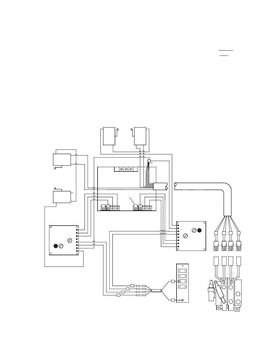
Fig. 4.10 Joystick Wiring Connections for Forklift Without TLC as Viewed from the Bottom of the Joystick
8.
Reconnect the wires from the upper drive
module (raise/lower) and lower drive module
(extend/retract) to the appropriate connector
strips as follows, Fig. 4.10.
• Gray wire to terminal “T”.
• Yellow wire to terminal “C”.
9.
Remount the joystick mounting cover to the
right side console.
10. Recheck boom speeds. If boom speeds are
still not within the specified times, pressure
settings in the hydraulic system must be
checked. Verify that boom raise, boom lower
and boom retract relieve at 2850 ±50 psi
(196,4 ±3,4 bar). Boom extend should relieve
at 2850 ±50 psi (196,4 ±3,4 bar).
4.3.6 Electronic Joystick Removal and
Replacement without TLC
The following instructions describe how to remove
and replace an electronic joystick without TLC
(Total Load Control). For a forklift with TLC refer
to the SKY TRAK TLC System Maintenance
Manual.
1.
Disconnect negative (–) cable from batteries.
2.
Remove capscrews from joystick console
cover, Fig. 4.11.
3.
Lift cover with joystick attached and secure in
raised position to assist in removal. Be
careful to avoid pulling harness connections
apart when lifting joystick and cover.
PA1123b