Warning – SkyTrak 6036 Service Manual User Manual
Page 239
Section 9
Hydraulic System
Model 6036/6036T S/N 9B0500 thru 14833
9-89
9.6.7 Steer Select Valve
a.
Removal
1.
Engage the park lock, place the travel selector
lever in neutral, and stop the engine.
2.
Slowly loosen fittings at steer select valve as
required (32, Fig. 9.52 or 9.53) to relieve any
trapped pressure.
3.
Remove the electrical connectors (32A) from
the solenoids (32B) on steer select valve (32).
Warning
Relieve hydraulic pressure before servicing any
hydraulic component. Escaping hydraulic fluid
under pressure can penetrate the skin causing
serious injury.
Warning
Wait for the hydraulic fluid to cool before servic-
ing any hydraulic component. Hot hydraulic fluid
can cause severe burns.
4.
To check a solenoid, apply 12 Vdc momentar-
ily to the solenoid leads and listen for an
audible click that indicates spool movement. If
there is no sound, the solenoid is probably
defective. Refer to Section 10 for additional
electrical test of the steer select valve.
NOTE: If no service is required for valve subplate
(30, Fig. 9.52 or 9.53), proceed to step 5.
5.
Tag and disconnect hydraulic hoses from
connectors (29) and elbow (28) on valve
subplate (30).
6.
Remove two nuts (29) and capscrews (31)
and remove assembled valve (32) and
subplate (30).
7.
Remove connectors (29) and elbow (28) from
the subplate.
e.
Installation
1.
Lubricate with hydraulic oil and install the
check valve, park lock release solenoid valve,
pressure reducing valve, and the sequence
valve into the brake manifold valve (Fig. 9.55).
2.
Install connectors (1 and 5), elbows (4),
reducer (7), and tee (8) into the brake manifold
valve.
3.
Install the assembled brake manifold valve on
the valve plate (9) using two capscrews (2)
and nuts (35).
4.
Connect the hoses to connectors (1 and 5),
elbows (4), and tee (8).
5.
Connect the electrical connector to the park
lock release solenoid valve (Fig. 9.55).
6.
Start the engine and operate the brake pedal
and park lock switch several time to purge the
brake system of air.
7.
Bleed the brake system as described in
paragraph (9.6.3.g) if necessary.
8.
Refer to paragraph 9.4.5.b for pressure
checks and adjustments, and paragraph
9.4.5.c for testing.
Warning
Before starting the engine be sure all hydraulic
connections are tight and all tools are removed
from the forklift.
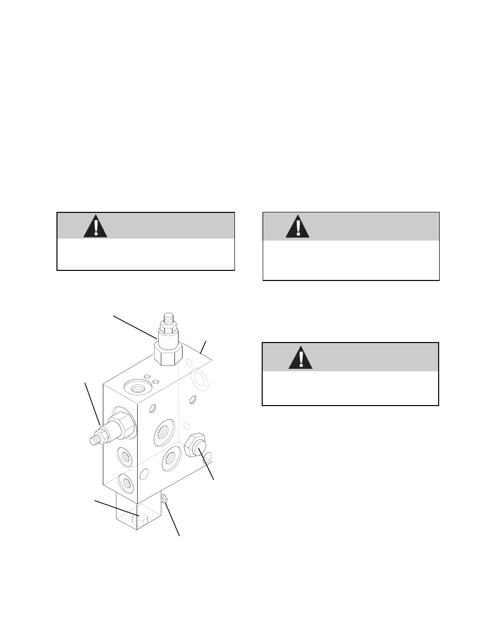
SEQUENCE
VALVE
PARK LOCK
RELEASE
SOLENOID
VALVE
35
Y
%5
&9
3
7
69
&
&
'6
CHECK
VALVE
BRAKE
MANIFOLD
VALVE
BLOCK
Fig. 9.55 Brake Manifold Valve Assembly
(With Trans. De-clutch S/N OE1180 and After)
PRESSURE
REDUCING
VALVE
SOLENOID ELECTRICAL
CONNECTIONS
MA5050