SkyTrak 6036 Service Manual User Manual
Page 162
Section 9
Hydraulic System
9-12
Model 6036/6036T S/N 9B0500 thru 14833
isolate the section from interference as supply or
load pressure changes. Under static conditions
the supply oil in the supply pressure passage acts
against the compensator spring which keeps the
valve closed. Whenever the main spool is shifted,
the combined spring pressure and load pressure
in the internal sensing passage open the compen-
sator spool. Oil flow over the compensator spool
land stabilizes when the pressure across the main
spool metering land and pressure of the compen-
sator spring are equal. An increase in supply
pressure acts on the compensator spool and
spring to close the spool and maintain constant oil
flow. A decrease in supply pressure acts on the
compensator spool and spring to open the spool
and maintain constant oil flow.
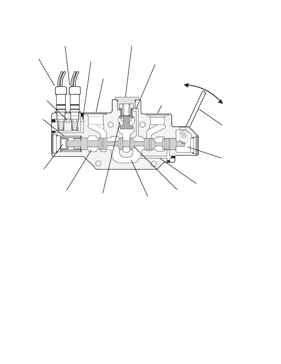
Fig. 9.8 Control Valve Working Section - Sectional View
PULSAR
SOLENOID
C1
PILOT
PRESSURE
MAIN-
SPRING
CYLINDER
PORT C2
PILOT TO
RESERVOIR
PULSAR
SOLENOID
C2
PRESSURE
COMPENSATOR
VALVE
CYLINDER
PORT C1
FLOW TO
PORT C1
FLOW TO
PORT C2
MANUAL
CONTROL
LEVER OR
BOLT
MK0060
CONTROL
CHAMBER
C2 PORT
LOAD PRESSURE
PASSAGE
CONTROL
CHAMBER
C1 PORT
RESERVOIR
PASSAGE
SUPPLY
GALLEY FOR
STACK
INTERNAL
PRESSURE
SENSE PASSAGE
LOAD SENSE
PASSAGE
MAIN
SPOOL
The main spools in the working sections are
designed for special flows. The metering lands for
both main spools have dual profile angles. This
allows proportionally more flow at lower operation
speeds and better control overall. The main
spools for the extend/retract section also permit
greater flow for boom extension versus boom
retraction; the ratio is approximately 2 to 1. All
main spools are spring loaded to be self-centering.
d. Working Sections - Individual Pressure
Compensation
Each working section of the control valve incorpo-
rates an individual compensator valve, Fig. 9.9, to