SkyTrak 6036 Service Manual User Manual
Page 226
Section 9
Hydraulic System
9-76
Model 6036/6036T S/N 9B0500 thru 14833
1
2
3
4
5
6
7
8
9
12
13, 14
16
17
18
19
20
21
22
23
24
25
27
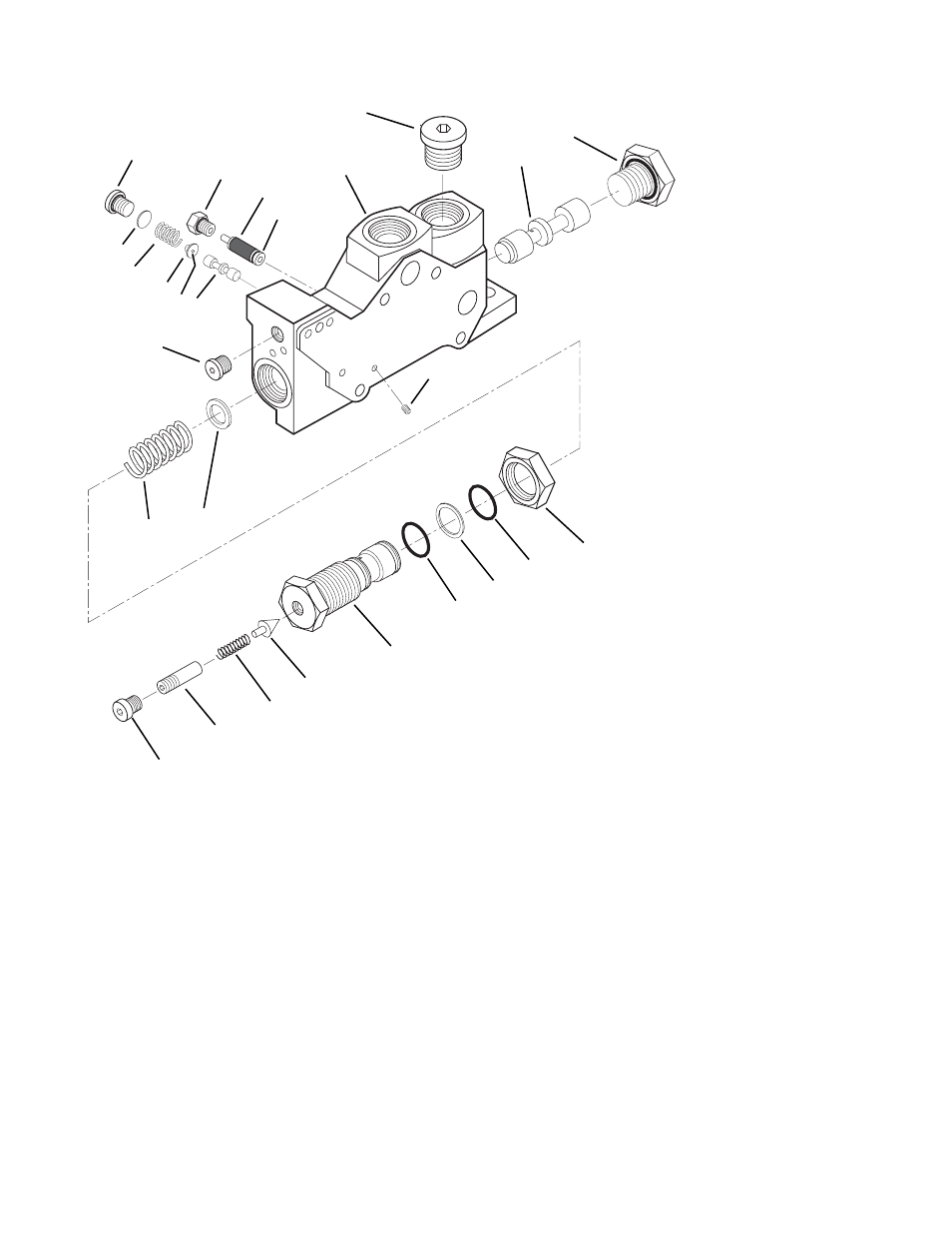
15. Inlet Valve Section
16. Spring
17. Washer
18. O-ring
19. O-ring
20. Backup Ring
21. Plug
22. Setscrew
23. Spring
24
Cone
25. Plug
26. Plug
27. Orifice Screw
26
15
11
10
1.
Plug
2.
Filter
3.
O-ring
4.
Pilot Reducing Spool
5.
Plug
6.
Pilot Shim
7.
Spring
8.
Guide
9.
Ball
10. Plug
11. Spool
12. Locknut
13. Seat
14. Adjustment Plug
MK0240
Fig. 9.45 Control Valve Inlet Section - Exploded View
NOTE: When removing the spool always pull the
spool out as straight as possible, as damage to the
spool and/or bore could occur.
3.
Insert a hooked tool into the spring guide and
pull the spool assembly (9) out of the valve
section. Remove plug (10) and O-ring (11).
Discard O-ring.
4.
To remove the override handle from the
working section remove set screw (12) and
pull knob (13), handle (6), nut (14) and
adapter (15) from the section. To remove
linkage, remove plug (16) and spring pin (17).
Pull shaft (18) and O-rings (19) from valve
section and clevis (20). Remove clevis and
dowel pin (21).
d. Disassembly of a Working Section
1.
Unscrew the pulsar solenoid cartridges (1, Fig.
9.46) from the section body. Using a pick,
remove the O-ring (2) from the bottom of the
solenoid cavity. Remove the disk (3) from the
cavity with a pencil magnet.
2.
Remove the retaining rings (4 & 5) from the
valve section using a snap ring tool. Thread
the manual override handle (6) or a 3/8-16 bolt
approximately 2 inches long, into the valve
section. Rotate the handle or bolt away from
the valve until the end plug (7) pops out.
Remove and discard the O-ring (8).