Warning – SkyTrak 6036 Service Manual User Manual
Page 287
Section 10.
Electrical System
10-25
Model 6036/6036T S/N 9B0500 thru 14833
3.
Attach one end of one jumper cable to the
positive terminal of the booster battery and
the other end of the same cable to positive
terminal of discharged battery. DO NOT
PERMIT vehicles to touch each other as this
could establish a ground connection and
counteract the benefits of this procedure.
4.
Attach one end of the remaining negative
cable to the negative terminal of the booster
battery and the other end to a ground at least
12 inches from the battery of the vehicle being
started. (DO NOT CONNECT DIRECTLY TO
THE NEGATIVE POST OF THE DEAD
BATTERY).
Any procedure other than the above could
result in:
• Personal injury caused by electrolyte squirt-
ing out the battery vent;
• Personal injury or property damage due to
battery explosion.
• Damage to the charging system of the
booster vehicle or of the immobilized vehicle.
Warning
2
3
4
5
1
6
7
MA1213
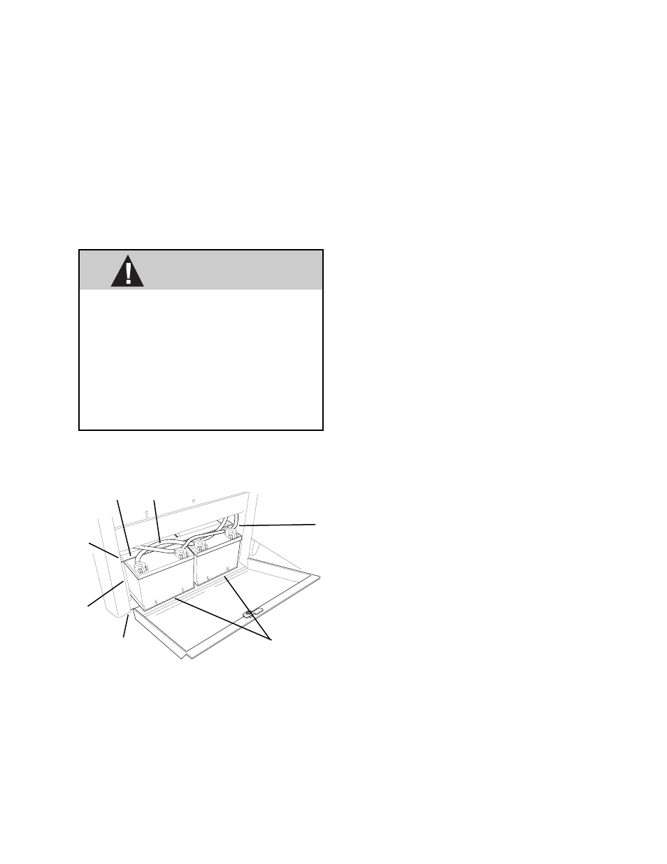
1. Positive (+) cable
2. Negative (–) cable
3. Two self-locking nuts (2)
4. Spacers (2)
5. Hold Down Strap
6. Bolts (2)
7. Batteries
Fig. 10.16 Battery Removal
h. Battery Removal
1.
Prepare to remove the battery(s) by unlocking
and opening door to battery compartment.
2.
Disconnect the negative cable (2, 10.16) from
the batteries.
3.
Disconnect positive cable (1) from batteries.
4.
Remove the two self-locking nuts (3) from
below the cab floor and lift the spacers (4),
hold down strap (5) and bolts (6) from the
battery compartment.
5.
Carefully lift the battery(s) from the battery
compartment.
i.
Battery Inspection, Cleaning and Drying
1.
Periodically look for any accumulation of dirt or
corrosion on top of the battery, corroded
terminals and cables, broken or loose terminal
posts, and container or cover that is broken or
cracked.
2.
Scrub the exterior of the battery and cable
terminals by using a nonmetallic brush which
has been dipped in a mixture of baking soda
and water.
3.
Dry the battery with a clean cloth.
4.
Check the voltage regulator setting at every
periodic maintenance inspection. Overcharg-
ing is a common cause of battery failure. The
voltage setting should be 13.6 to 13.8, and
never more than 14.0 V.
j.
Battery Installation
1.
Place batteries in battery compartment.
2.
Install bolts (6, Fig. 10.16), spacers (4), hold
down strap (5), and two self-locking nuts (3).
DO NOT OVERTIGHTEN. Be sure hold-down
strap is properly attached to keep batteries
from bouncing. Vibration is very harmful to a
battery.
3.
Connect positive (+) cable (1) to the batteries.
4.
Connect negative (–) cable (2) to batteries.
5.
Close and lock door to battery compartment.
k.
Service Test Specifications
• Load Test Amperage is 260.
• SAE/BCI reserve capacity in minutes is 95
minutes.
• Cold cranking current (SAE SPEC J537h) is
525 A at 0 °F (–18 °C)
• For battery warranty contact your local Delco
distributor.