Warning – SkyTrak 6036 Service Manual User Manual
Page 129
Section 8B
Cummins Engine
Model 6036/6036T S/N 9B0500 thru 14833
8B-9
• It is necessary to put the engine in the “Run”
position. Because the engine may start, be
sure to follow all the safety precautions. Use
the normal engine starting procedure.
• When using the starting motor to vent the
system, do not engage it for more than 30
seconds at a time; wait two minutes between
engagements.
30
0
15
45
RUN
STOP
Controlled venting is provided at the injection
pump through the fuel drain manifold, Fig. 8B.16.
Small amounts of air introduced by changing the
filter elements or injection pump supply line are
vented automatically, if the fuel filter is changed in
accordance with the instructions.
Warning
Do not bleed air from a hot engine as this
could cause fuel to spill onto a hot exhaust
manifold creating a danger of fire.
Fig. 8B.17 Operating the Plunger on the Lift Pump
MA1840
FUEL LIFT PUMP
LOW PRESSURE LINE
VENT SCREW
Warning
BOSCH
CAV
MA1800
1.
To vent the low pressure lines and fuel
filter(s):
• Open the vent screw, Fig. 8B.17.
• Operate plunger on lift pump until the fuel
flowing from the fitting is free of air, Fig.
8B.17.
• Tighten the vent screw and torque it to
6 lb-ft (8 Nm), Fig. 8B.17.
Fig. 8B.16 Fuel Drain Manifold
Fig. 8B.19 Pumping from Fuel Lift Pump
MA1830
MA1690
MA1670
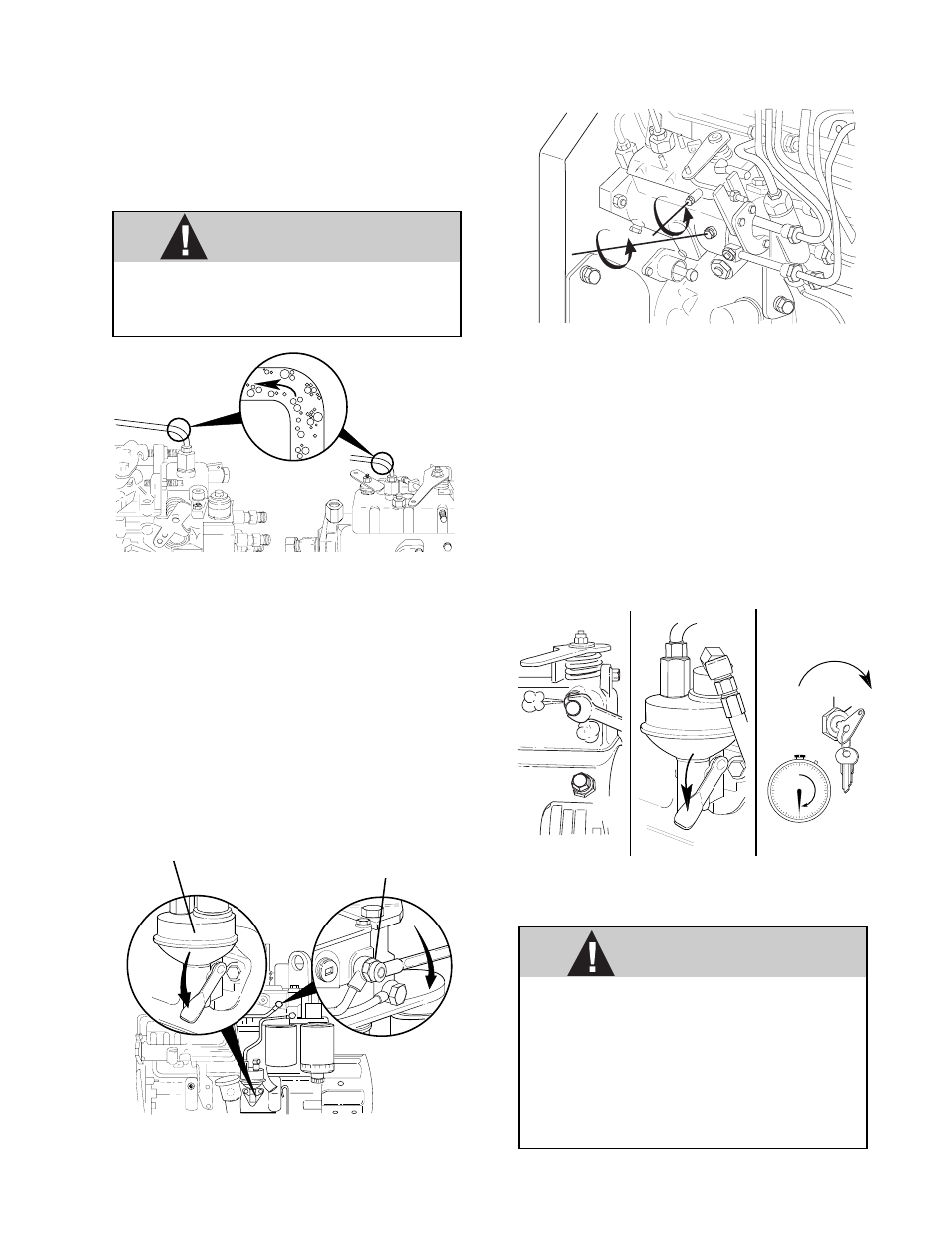
2.
Bleed the Lucas CAV injection pump at the
locations shown in Fig. 8B.18. Bosch pumps
do not need bleeding at the pump.
3.
Air/fuel can be pumped from this location, Fig.
8B.19, with the hand lever on the lift pump if
the fuel solenoid valve is energized. This
procedure will work for the Lucas CAV injec-
tion pump only.
Fig. 8B.18 Venting Air from Lucas CAV Injection
Pump
MA2050