SkyTrak 6036 Service Manual User Manual
Page 176
Section 9
Hydraulic System
9-26
Model 6036/6036T S/N 9B0500 thru 14833
9.4.5
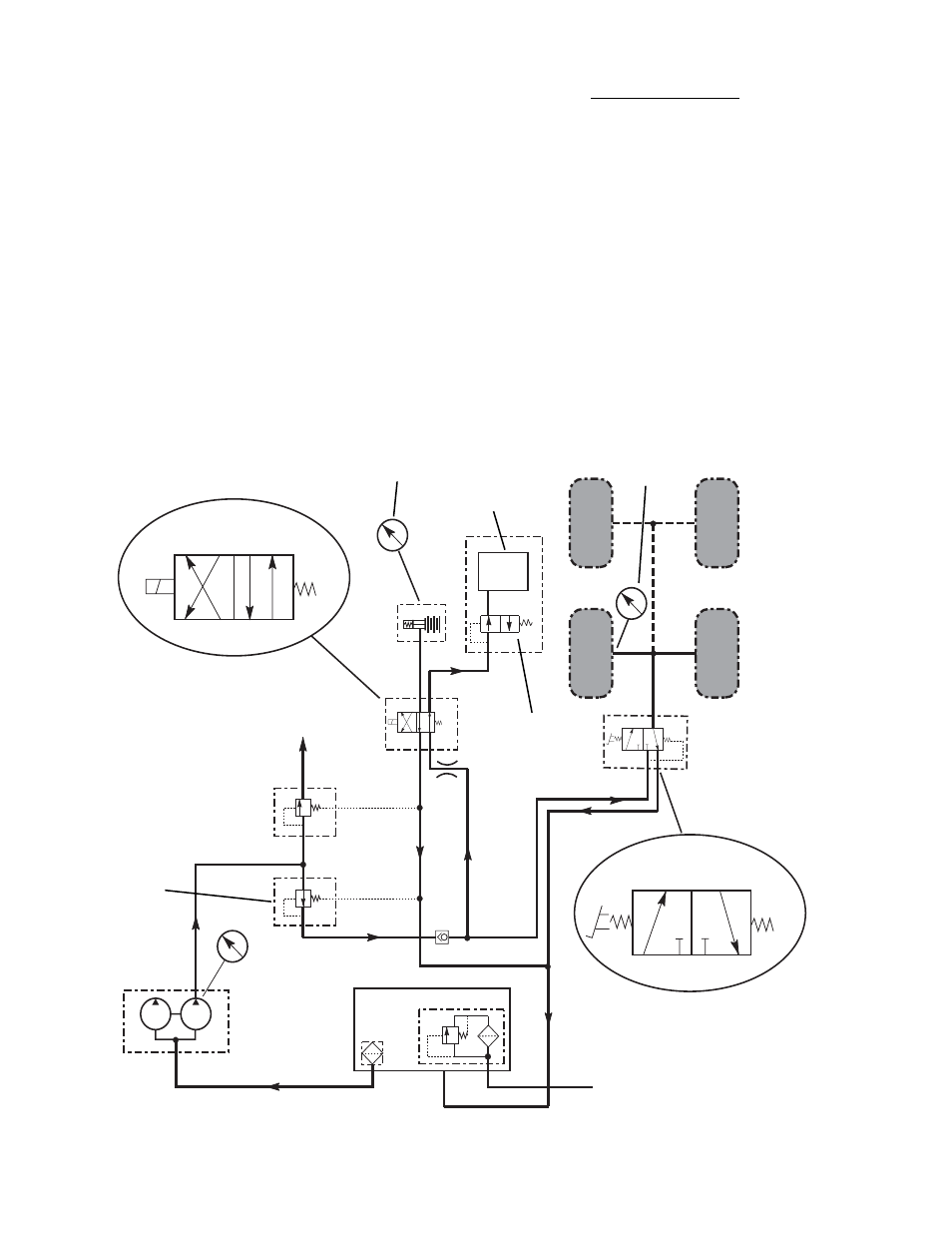
Brake Circuits
(S/N OE1180 and After –
With Trans. De-Clutch)
a.
Description
Hydraulic pressure is normally applied in the
service and park lock brake circuits by the 15 gpm
section (front half) of the tandem pump, which
draws its fluid through a suction strainer in the
reservoir, Fig. 9.15. A pressure of 610 - 660 psi
(42 - 45,5 bar) is maintained by the sequence
valve. This pressure is reduced to 525 ± 25 psi
(36,2 ± 1,7 bar) at the pressure reducing valve
prior to entering the solenoid-operated park lock
release valve and pedal-operated service brake
valve.
0-1000 PSI
PRESSURE
GAUGE
MA3060
Fig. 9.15 Brake Circuit – With De-Clutch
Service Brake Valve
When the brake pedal in the operator’s cab is not
depressed, the brake valve spool is spring-
positioned so that hydraulic flow is blocked at port
C, Fig. 9.15, no pressure is applied to the service
brakes. Return flow from the service brakes
passes through ports B to D to the reservoir.
When the brake pedal in the operator’s cab is
depressed, the brake valve spool is positioned so
that flow is directed through ports C to A, Fig.
9.15, to the service brake pistons. As pressure is
applied, the pistons press the brake discs together
slowing or stopping the wheel. The brake pedal
will return to the up position when released.
TRANSMISSION
DE-CLUTCH
VALVE
0-1000 PSI
PRESSURE GAUGE
INSTALLED IN PARK LOCK BLEEDER
TRANSMISSION
PRESSURE
REDUCING
VALVE 525
±
25 PSI
PARK LOCK RELEASE VALVE
TANDEM
PUMP
15
GPM
30
GPM
0-1000 PSI PRES-
SURE GAUGE
CHECK VALVE
SEQUENCE
VALVE 610-660
PSI
A
B
A
B
DISENGAGED
ENGAGED
D
C
D
C
TO POWER
STEERING
UNIT
A
B
BRAKES NOT
APPLIED
BRAKES
APPLIED
D
C
D
C
SERVICE BRAKE VALVE
SERVICE BRAKE
VALVE 525 ± 25
PSI
PARK
LOCK
RESERVOIR
STAINER
RETURN FILTER
FROM THE CONTROL
VALVES