SkyTrak 6036 Service Manual User Manual
Page 236
Section 9
Hydraulic System
9-86
Model 6036/6036T S/N 9B0500 thru 14833
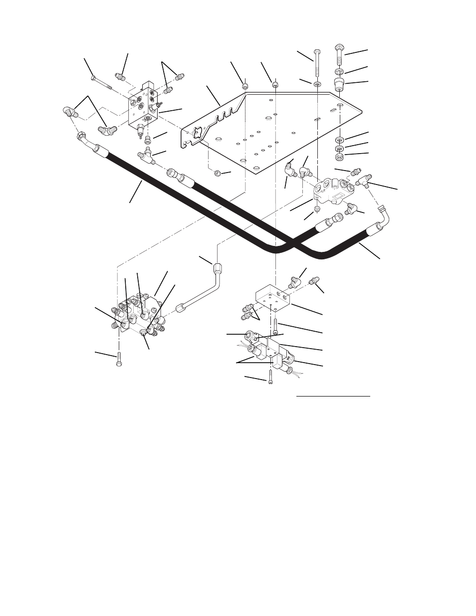
Fig. 9.53 Valve Plate Assembly (with De-Clutch) - Exploded Underside View (S/N OE1180 and After)
1.
Connector
2.
Capscrew (2)
3.
Brake Manifold Valve
4.
Elbow (2)
5.
Connector (2)
6.
Washer (2)
7.
Reducer
8.
Tee
9.
Valve Mounting Plate
10. Locknut (3)
11. Locknut (4)
12. Capscrew (2)
13. Carriage Bolt (4)
14. Bolt Retainer (4)
15. Rubber Mount (4)
16. Washer (4)
17. Lock Washer (4)
18. Hex Nut (4)
19. Elbow (2)
20. Elbow
5
B
2
6
11
12
14
15
13
16
17
18
19
22
21
5
24
19
27
26
7
8
4
29
30
31
33
32B
32B
32A
32C
L
1
3
C
R
9
10
A
D
E
20
F
G
H
I
28
29
J
K
32
34
25
23
P
O
MA5030
Q
HOSE CONNECTIONS
A.
To Pump Outlet
B.
To Brake Valve (Top Port)
C.
To Park Brake
D.
To Hydraulic Tank
E.
To Steering Unit (Port “P”)
F.
To Steering Unit Outlet
G.
To Brake Valve (Bottom Port)
H.
To Steering Unit (Port “R”)
I.
To Left Front Steering Cylinder
J.
To Left Rear Steering Cylinder
K.
To Right Rear Steering Cylinder
L.
To Steering Unit (Port “T”)
M. To Frame Tilt “Right”
N.
To Frame Tilt “Left”
O.
To Grille Tilt “Forward”
P.
To Grille Tilt “Backward”
Q.
To Hydraulic Filter
R.
To Transmission De-clucth
35
21. Locknut (4)
22. Priority Valve
23. Tube Assembly
24. Tee
25. Control Valve Frame and
Fork Tilt
26. Hose Assembly
27. Hose Assembly
28. Elbow
29. Connector (3)
30. Subplate
31. Capscrew (2)
32. Steer Select Valve
32A. Electrical Connector
32B. Solenoid
32C. Screw (4)
33. Capscrew
34. Capscrew
35. Nut (2)
M
N