4 park lock switch – SkyTrak 6036 Service Manual User Manual
Page 292
Section 10.
Electrical System
10-30
Model 6036/6036T S/N 9B0500 thru 14833
d. Inspection and Replacement
1.
Inspect the switch terminals for continuity and
shorting in the ENGAGED and DISENGAGED
positions.
2.
Replace switch if it fails the tests in step 1.
e.
Installation
1.
Connect electric wires as tagged during switch
removal.
2.
Position park lock switch, Fig. 10.21, under
panel.
3.
Position switch guard over switch stem.
4.
Install hex nut and hex nut cap seal.
5.
Connect negative (–) cable (2, Fig 10.16) to
batteries.
6.
Prepare to test park lock engagement and
disengagement by clearing the area around
the forklift of persons and any obstructions to
forklift travel.
• To test for engagement, engage the park
lock switch, place the drive in forward or
reverse and second or medium gear and
apply full throttle. The forklift should
remain motionless in both forward and
reverse positions.
• To test for disengagement, firmly depress
service brake pedal, disengage park lock
switch, place drive in forward or reverse
and first or low gear, and slowly press the
throttle pedal while releasing the brake
pedal. The park lock should release and
the forklift should be free to travel.
10.7.4
Park Lock Switch
The park lock switch, Fig. 10.21, has two posi-
tions, engaged and disengaged. To engage, lift
cover and flip lever up. To disengage, lower
switch cover.
a.
Removal
1.
Disconnect negative (–) cable (2, Fig. 10.16)
from batteries.
2.
Prepare to remove park lock switch, Fig.
10.21, by removing the lower panel which is
located below the switch.
3.
Tag and disconnect electric wires from the
switch.
4.
Remove hex nut cap seal and the hex nut
which secures switch to left front console
panel.
5.
Remove switch guard.
b. Disassembly
Do not disassemble the park lock switch.
c.
Cleaning and Drying
1.
Clean and condition the hex nut cap seal
using an appropriate vinyl cleaner.
2.
Without submerging the switch, clean the
switch with an approved solvent and dry with
a clean lint-free cloth.
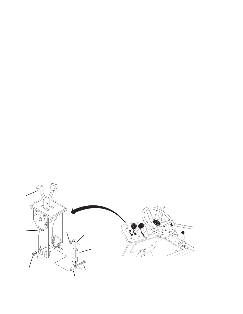
7.
Spacer
8.
Plate
9.
Transmission Shifter
Fig. 10.22 Reverse Switch
N
R
F
DANGE
R
1.
Cotter Pin
2.
Washer
3.
Hex Nut
1
2
4
5
3
6
7
8
9
4.
Lock Washer
5.
Washer
6.
Capscrew
REVERSE
SWITCH
MA1261