Channel creation example, Channel creation example -14 – Agilent Technologies Agilent E5250A User Manual
Page 150
6-14
Agilent E5250A User’s Guide, Edition 11
Programming the E5250A
Programming Examples
Channel Creation Example
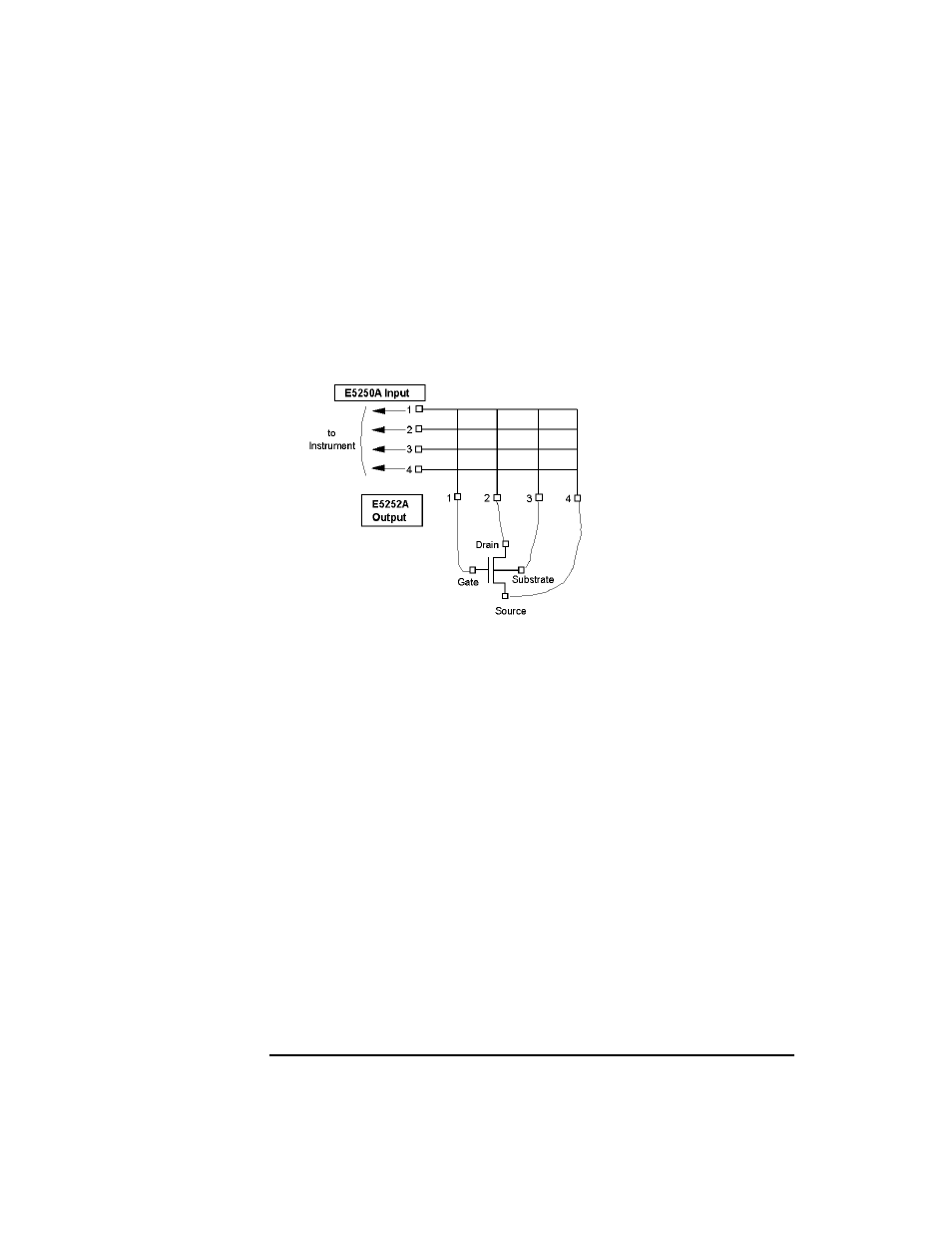
The following example is a typical control program for the E5250A with the
E5252A, which connects instrument output to DUT as shown in Figure 6-1. Bias
Mode and Couple Port are not used in this example.
Figure 6-1
MOSFET Connection Example
Required
Conditions:
This program assumes the following conditions.
E5250A Installed Cards:
•
Slot 1: E5252A
•
Slot 2 to 4: not used.
E5250A Input Ports:
•
SMU INPUT 1 to 4: should be connected to instrument.
•
SMU INPUT 5 to 6: not used.
•
AUX INPUTs: not used.
E5252A Output Ports:
Output 1 to 4 are used in the program, and should be connected as follows.
•
Output 1: Gate
•
Output 2: Drain
•
Output 3: Substrate
•
Output 4: Source