Internal boot mode, External boot mode, Internal boot mode -2 external boot mode -2 – Cirrus Logic EP73xx User Manual
Page 76
6-2
EP7309/11/12 User’s Manual - DS508UM4
Copyright Cirrus Logic, Inc. 2003
Processor Support
6
Internal Boot Mode
The 128 bytes of on-chip Boot ROM contain an instruction sequence that configure
UART1 to receive up to 2 Kbytes of serial data which is then placed in the on-chip
SRAM. Once the download is complete, the program counter jumps to SRAM to
begin executing the downloaded data. The purpose of this mode is to allow the
downloaded code to facilitate programming of FLASH or other ROM device. See
for code details.
Selection of the internal Boot ROM is accomplished by setting
nMEDCHG
(active low)
before power-on-reset. The value read is latched at the rising edge of
nPOR
.
The processor at power-on-reset is in Standby state in this mode and
WAKEUP
must
be asserted in accordance with the power-up sequence to wake up the processor and
put it into Operating State.
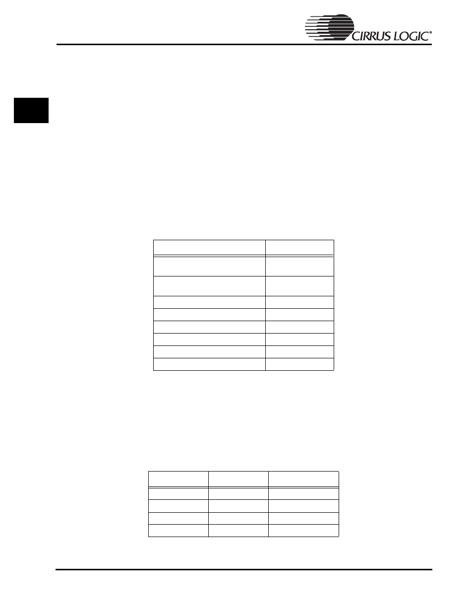
The memory map is as follows:
External Boot Mode
Normal boot mode here involves the processor sensing that
nMEDGHG
is not active
and then checks for boot width by looking at the pin values on
PE[1:0]
to determine
the width of the boot device.
below is the interpretation by the processor.
Table 6-1: Chip Select Address Ranges for On-Chip Boot ROM
Address Range
Chip Select
0000.0000–0FFF.FFFF
CS[7]
(Internal only)
1000.0000–1FFF.FFFF
CS[6]
(Internal only)
2000.0000–2FFF.FFFF
nCS[5]
3000.0000–3FFF.FFFF
nCS[4]
4000.0000–4FFF.FFFF
nCS[3]
5000.0000–5FFF.FFFF
nCS[2]
6000.0000–6FFF.FFFF
nCS[1]
7000.0000–7FFF.FFFF
nCS[0]
Table 6-2: Boot Options
PE[1]
PE[0]
Boot Block (nCS0)
0
0
32-bit
0
1
8-bit
1
0
16-bit
1
1
Undefined