Cpu state control, Standby state, Clock status – Cirrus Logic EP73xx User Manual
Page 38: Cpu state control -12, Figure 2-4. state diagram -12
2-12
EP7309/11/12 User’s Manual - DS508UM4
Copyright Cirrus Logic, Inc. 2003
CPU Core
2
internal PLL is not used. The default value “00” for the PLL setting in SYSCON3 must
not change.
CPU State Control
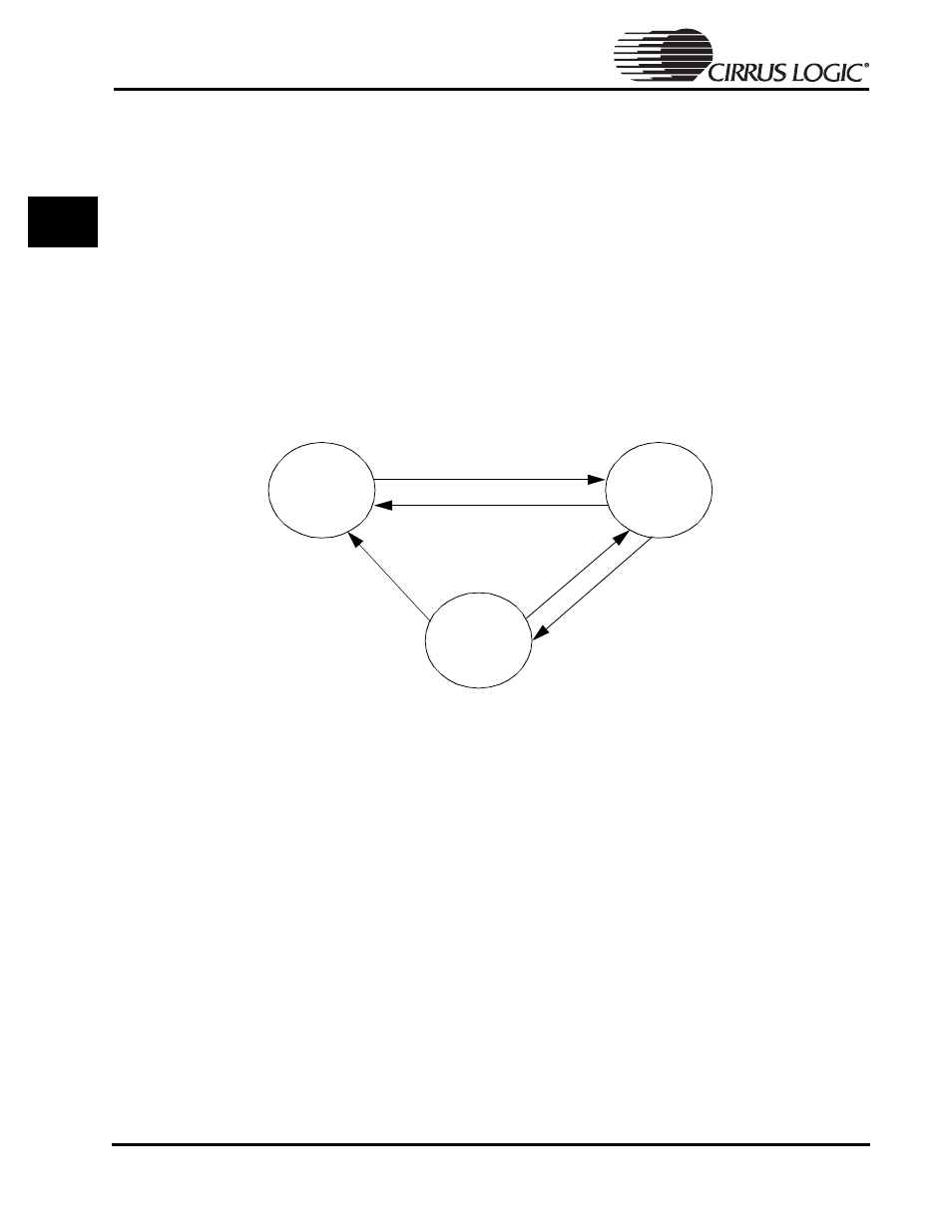
There are three principal power management states on the EP73xx processor
• Operating State (highest power consumption)
• Idle State
• Standby State (lowest power consumption)
Each state leaves on or turns off a unique set of CPU peripherals which can serve to
reduce or limit the power required for the system for blocks of time in which there is
no external system activity. The processor can enter or exit any one of the three states.
Standby State
Standby state is the lowest power state the processor can achieve and still be capable
of returning to operating state or equates to the system being switched off. The RTC
clock remains on to insure that the processor can “wake up” from an external
interrupt or the “wake up” signal.
When the EP73xx is first powered on, the processor is in a “cold reset”. The same
condition can be created by asserting
nPOR
. Cold reset for the processor is the
standby state. In this instance, none of the peripherals have been initialized so the
only method for entering the operating state is by means of the
WAKEUP
pin.
Clock Status
• If internal PLL is used, it will shut off
• If external 13 MHz clock is being used, CPU will ignore input. External
Figure 2-4. State Diagram
Standby
Operating
Idle
Interrupt or rising wakeup
Write to standby location,
power fail, or user reset
In
te
rr
up
t
Write to halt location
nPOR, power fail,
or user reset