Debug modes, Oscillator and pll bypass mode, Oscillator and pll test mode – Cirrus Logic EP73xx User Manual
Page 115: Debug modes -3, Table 14-2: ep73xx hardware test modes -3
EP7309/11/12 User’s Manual - DS508UM4
14-3
Copyright Cirrus Logic, Inc. 2003
JTAG Interface
1414
14
Debug Modes
The EP73xx supports a number of hardware activated test modes, these are activated
by the pin combinations shown in
. All latched signals will only alter test
modes while
nPOR
is low, their state is latched on the rising edge of
nPOR
. This
allows these signals to be used normally during various test modes.
Within each test mode, a selection of pins is used as multiplexed outputs or inputs to
provide/monitor the test signals unique to that mode.
Oscillator and PLL Bypass Mode
This mode is selected by
nTEST0
= 1,
nTEST1
= 0.
In this mode, all the internal oscillators and PLL are disabled, and the appropriate
crystal oscillator pins become the direct external oscillator inputs bypassing the
oscillator and PLL.
MOSCIN
must be driven by a 36.864 MHz clock source and
RTCIN
by a 32.768 kHz source.
Oscillator and PLL Test Mode
This mode is selected by
nTEST0
= 0,
nTEST1
= 1, Latched
nURESET
= 0
This test mode will enable the main oscillator and will output various buffered clock
and test signals derived from the main oscillator, PLL, and 32 kHz oscillator. All
internal logic in the EP73xx will be static and isolated from the oscillators, with the
exception of the 6-bit ripple counter used to generate 576 kHz and the Real Time
Clock divide chain. Port A is used to drive the inputs of the PLL directly, and the
various clock and PLL outputs are monitored on the COL pins.
defines the
EP73xx signal pins used in this test mode. This mode is only intended to allow test of
the oscillators and PLL. Note that these inputs are inverted before being passed to the
PLL to ensure that the default state of the port (all zero) maps onto the correct default
state of the PLL (TSEL = 1, XTALON = 1, PLLON = 1, D0 = 0, D1 = 1, PLLBP = 0). This
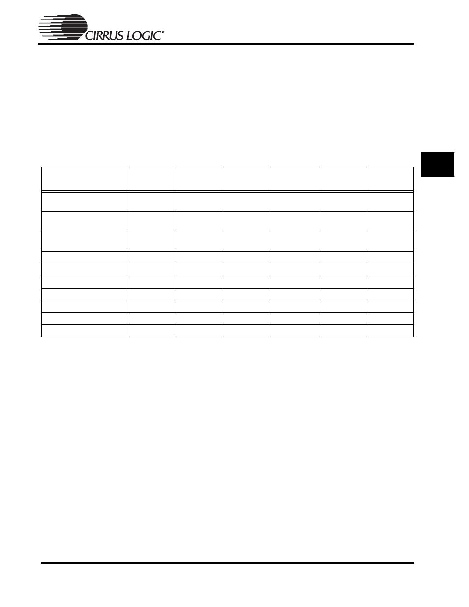
Table 14-2: EP73xx Hardware Test Modes
Test Mode
Latched
nMEDCHG
Latched
PE[0]
Latched
PE[1]
Latched
nURESET
nTEST[0]
nTEST[1]
Normal operation
(32-bit boot)
1
0
0
X
1
1
Normal operation
(8-bit boot)
1
1
0
X
1
1
Normal operation
(16-bit boot)
1
0
1
X
1
1
13 MHz divided by 4
1
1
1
X
1
1
Alternative test ROM boot
0
X
X
X
1
1
Oscillator / PLL bypass
X
X
X
X
1
0
Functional Test (EPB)
0
X
X
1
0
1
Oscillator / PLL test mode
X
X
X
0
0
1
ICE Mode
X
X
X
1
0
0
System test (all HiZ)
X
X
X
0
0
0